I have a morbid sense of humor. And I’m also a firm believer in not wasting any time in life; choosing to focus making the most of the time I have, creating new and interesting things. But even I need a reminder sometimes, and that’s where the “Death Clock” comes in.
No, not the cartoon metal band. What I’m talking about is a giant clock counting down until the day I’ll (likely, based on life expectancy averages) die. Like I said; morbid sense of humor. But I choose to see it as a daily reminder that life is short and there’s no sense in wasting any of it.
This project really started from a fascination with 7-segment displays and wanting to make a really large display. I knew I wanted one but not why at first… then the countdown idea struck me and it’s stuck ever since. Sure, giant 7-segment displays have been made many times before but that’s just an opportunity to do mine different.
For one, basically all that I’ve ever seen use the standard strip LEDs that we all know and love. One of the best I’ve seen was made by John Park @ Adafruit and uses multiple layers of acrylic to form and diffuse the segments. I absolutely loved the look, and considered replicating it but, no, I’ve got to do my own thing ;) Then I remembered seeing 8mm bulb style WS2812 LEDs. They look just like the old analog RGB LEDs, with 4 pins and everything. Except that the pins are 5V, ground, data in, and data out. In reality, they aren’t WS2812 at all, but APA106-F8 which are protocol compatible. Digital LEDs is a confusing landscape ;)
So, these gave me the idea of trying to replicate an old bulb-style 7-segment digit, like you would’ve seen on an old stadium score board or the original NASA launch countdown.
Next step was, of course, CAD modeling a single digit. I wanted it have the same slight slant that most 7-segment displays had which definitely complicated things a bit. I settled on a 7° tilt as looking right. To get ahead of the process a bit, I wanted to create some custom PCBs that would make assembling the digit really easy. I had the idea to give each one a 90° point so that each of the segments could be flush fit together and soldered. But since I had a 7° slant, that meant I would have to tilt the point by 3.5° in opposing directions to make everything work out.
Clear as mud, right? Yeah, I thought so too and this is why I modeled it all in CAD. The basic point is that I wanted the PCBs to work unmodified for all segments and I realized that by adding those opposing angles to each point I could use the PCB either “face up” or “face down” and have all possible orientations. Here, take a look:
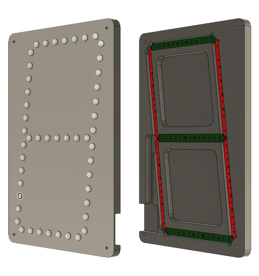
The green and red faces of the modeled PCBs specify which face is up. More about how all these connect in a bit.
The display was designed so that it could be CNC routed out of 12mm thick sheet material and have all the PCB’s snuggly fit, with the LEDs poking through to the front, being the only thing that can be seen.
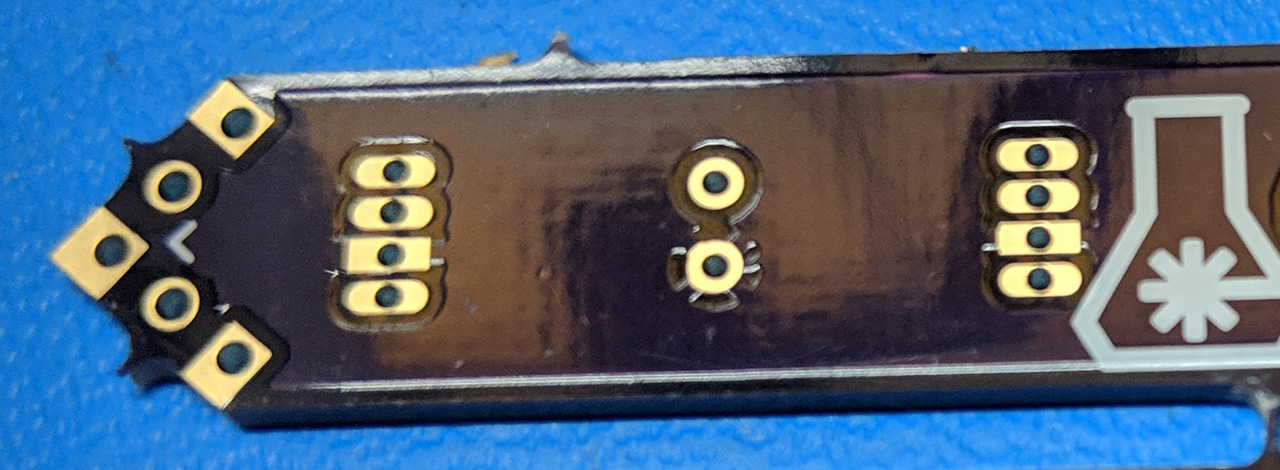
With that sorted out, I was confident enough to design the PCBs in KiCAD and ship them off to OSHPark. They really aren’t all that complicated as they just pass the LED data signal from one LED to the next and provide power. The tricky bit is in that 45° point. It has 5 pads on it, mirrored around the center point pad, which is ground. The middle pad on each side is data (in or out, depending on side of PCB) and the outer pad on each side is 5V.
The full KiCad project can be found on GitHub.
By using the above described pad orientation, the correct pads will always line up no matter how you orient the PCB. With exception of data direction, of course. The ground and 5V pads are always solder-jumped across while the data pad is only connected as data flow is required.
As mentioned earlier, I had to solder some “face up” and others “face down”, as shown below:
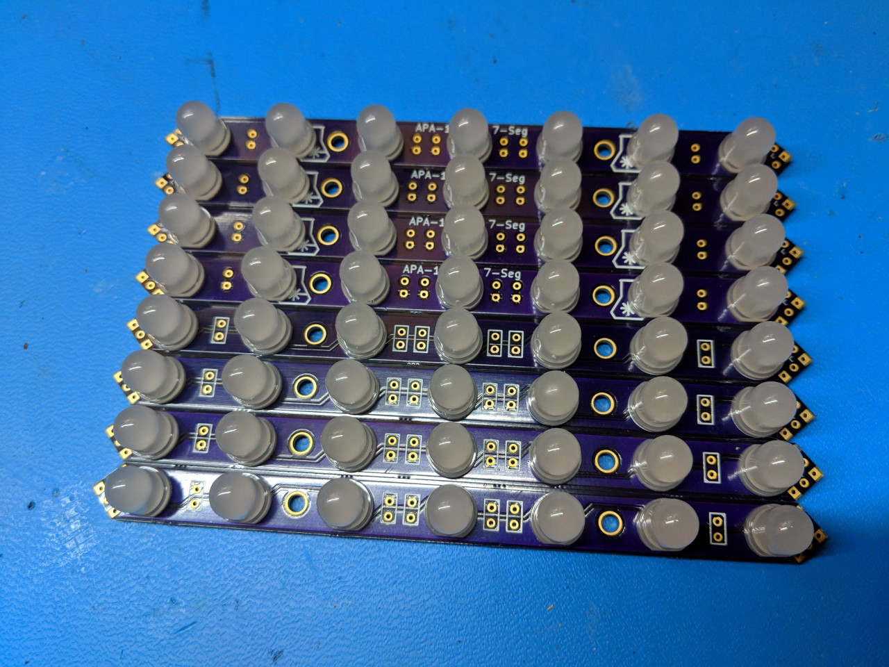
Yes, there are 8 instead of 7. 4 of one orientation and 3 of the other were needed and I couldn't remember which at the time.
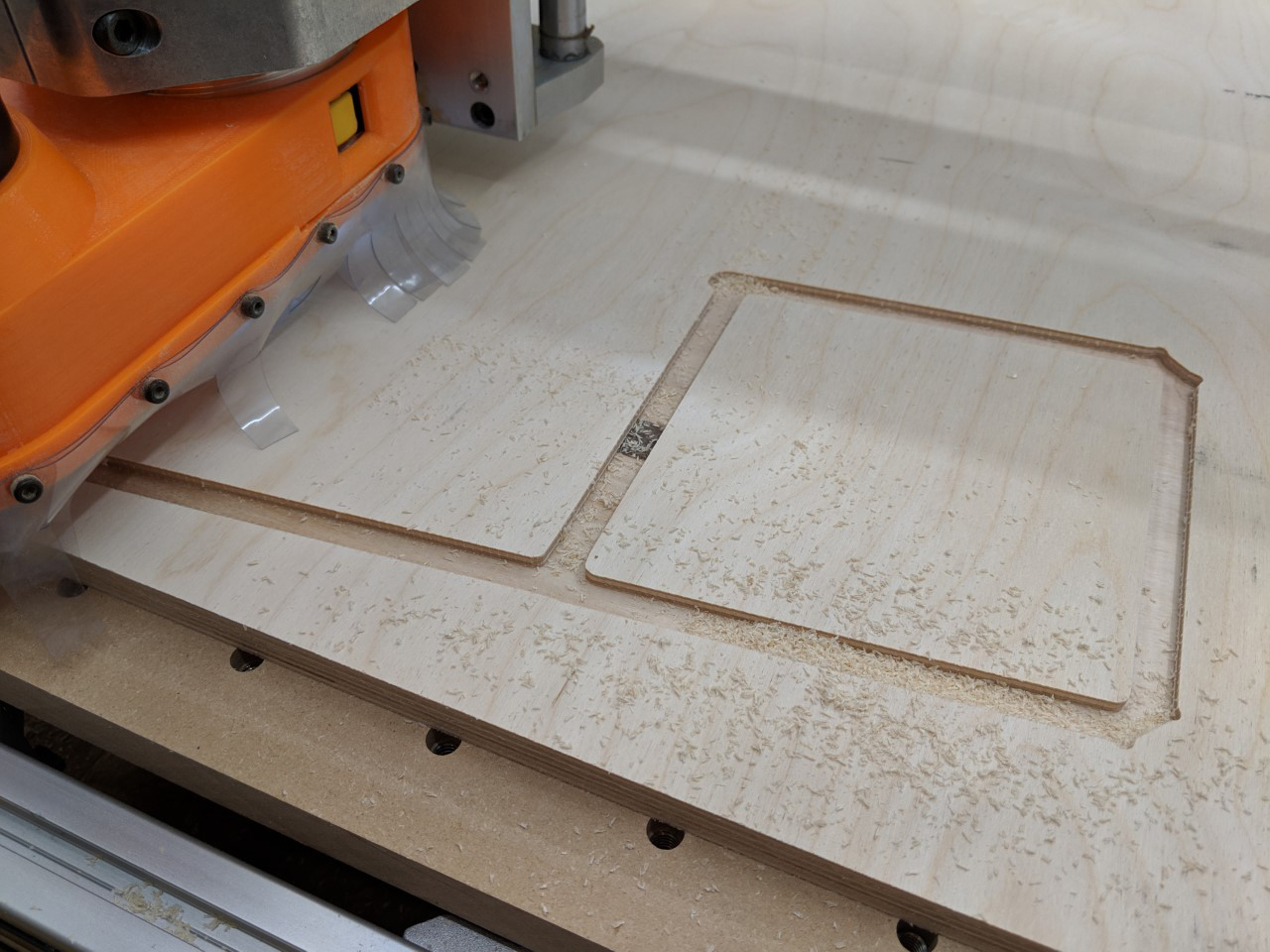
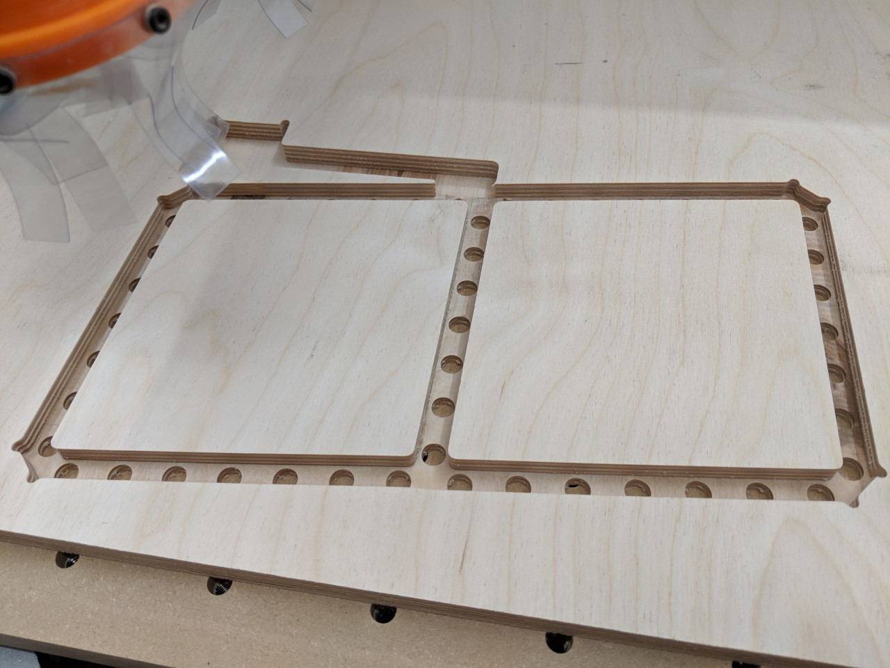
With these soldered and functionality confirmed, I could move on to creating the frame of the display over on the CNC. This was all prepared in Fusion 360, of course and you can download the project including all the CAM processes on GitHub.
I’m no expert on CNC and CAM, so I’ll just leave some pictures of it in process and fully routed for you to enjoy :)
If you want to learn more about these things, I highly recommend checking out NYC CNC, Lars Christensen and Winston Moy on YouTube. They taught me everything I know :)
One thing I will say is that the original plan was to use MDF for this part, mainly because it’s cheap. But after having to do some seriously cleaning on the CNC from all the CNC dust, I’ve got to say the cost savings isn’t worth the other costs you will pay. MDF is nasty, terrible stuff. What I found instead was a local supplier of high quality Baltic birch plywood. This isn’t your big box store junk plywood… this 12mm (yes, it’s metric!) sheet has 9 plys with no voids! And seriously, it’s a dream to cut. Just look back at the picture above and note how it produces actual chips, and not fine dust. Don’t think I’m ever going back.
Though, as I write this I realized it might have made more sense to laser cut everything. I could use thinner 3mm or 6mm material for the front panel and just cut holes. The holes will align all the PCBs via the LEDs and once everything is soldered together, it’s really not going anywhere. Then just cut a spacer frame to offset a back-plate and it’s good to go. But hey, that’s why this is a prototype and this is only “Part 1” :)
Anyways, speaking of assembly, now is time to put the PCBs in the frame!
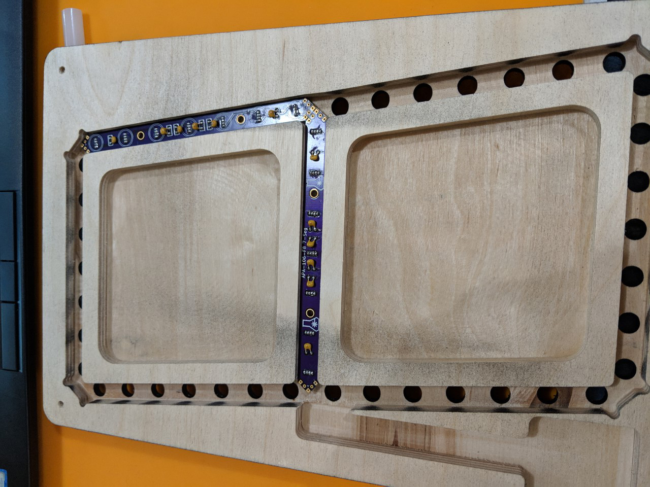
Above I show two segments installed and ready to be soldered. At this point, however, I realized I needed to be extra careful about the direction of the dataflow and, as you can see, added some annotation to the frame to make sure I didn’t forget.

As you can see the LED data flows around in, well, a figure 8 pattern. Entering on one side and exiting on the other, eventually connecting to more digits in the chain. I had to also be careful to reference by CAD model frequently so that I know where to use “face up” and where to use “face down” segments. Though, because of that opposing 3.5° offset points it would actually be hard to install them incorrectly.

Last was to install the controller for this whole party. In the picture above, I’m using an Adafruit Pro Trinket. Which worked fine for initial testing but, once I really started playing, it ended up being replaced with a Teensy 3.2 - Same size and an order of magnitude more power!
Fortunately I had the foresight to install a connector instead of just directly soldering everything. In the final display this will most certainly be swapped out for an internet connected device so that, if nothing else, it can always have the correct time. But as this was to act as a mobile demo (more on that shortly), I didn’t want to have any requirements on a WiFi connection.
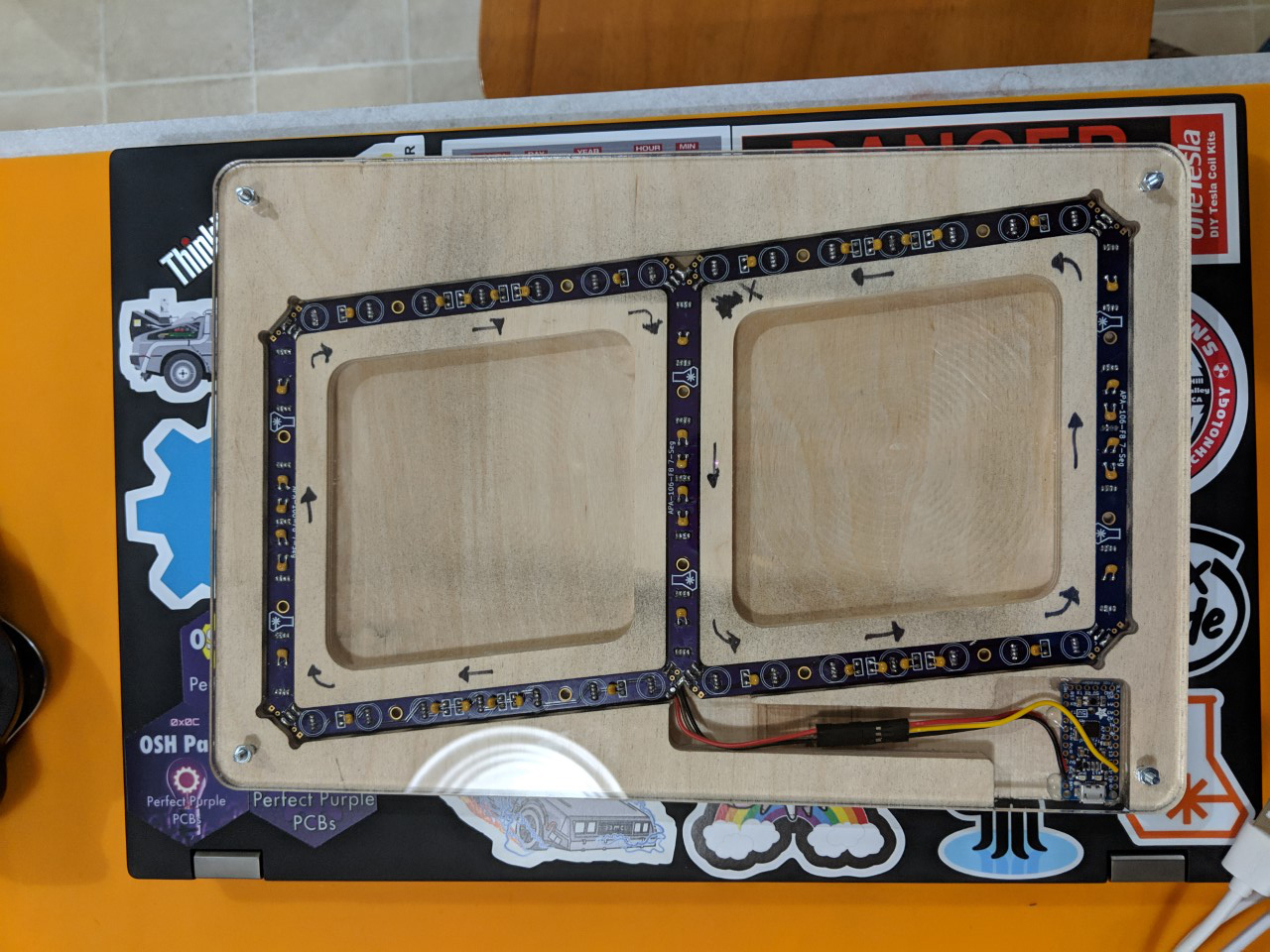
Last but not least it all got topped off (well, “backed off” in this case) with a laser cut, clear acrylic back panel to protect everything while letting it all be seen. While this is primarily a prototype for the final display, Dan and I are going to be at the inaugural KiCon this weekend (Apr 26 & 27, 2019) and I’ve got to have something fun to show off! So being able to see those perfect purple PCBs was of course high priority ;)
I won’t get deep into the code here as it’s all just simple stuff to test the display. You can check it out on GitHub of course if you would like. Instead, I’ll jump straight to the good stuff; the video:
So, there it is. In all it’s rainbow digit glory. I’ll have a more in-depth write-up on the code after the final display is made. This post is already in-depth enough as it is. Maybe someday I’ll write a project post that’s under 1000 words… unlikely though.
It’s still a work in progress of course, but fell free to check out all the files for everything done so far on the DeathClock GitHub repo.
Happy making! :)