Try as I might, writing about the things I make is just never as easy as making them. I must’ve started this post a dozen times already and then forgotten about it. Assuming I actually finish this time, I’m only be a year late writing about it 😕
What I’m talking about is what I call the “POVSaber”… Or Persistence of Vision Light Saber. Who doesn’t want a light saber after all?
This was one of those projects that ruminated on the project back burner for nearly 5 years. While not true now, like the Bixel, this was a project that was the culmination of nearly all that I had learned up until that point. More specifically it was really the first project for which I had done a complete and complex CAD model of the entire project. But more on that later.
Design
The seed of this project came from seeing one of those 144 pixel per meter LED strips for the first time. Even without the POV idea, I immediately thought an LED strip like that was perfect for building a light saber, given the pixel density. The high quality light sabers you can build are nice and all but typically just have as single LED in the hilt that illuminates the blade. The blade doesn’t actually “grow” like the real deal.
Hardware
Originally I was going to use WS2812 LEDs as, at the time, they were the only type to come in that pixel density. But by last year when I finally started the project APA102/SK9822 strips were available. While they required an extra pin to control they are much more suitable for persistence of vision applications which I had decided would be a great feature to have.
With POV as a goal that also meant I needed the power to drive it all. While my choice of the Teensy 3.6 is probably overpowered I ended up choosing it because it also included a built-in micro SD card slot. This would allow me to store the animations and POV images on the card as little more than bitmap files (not exactly, more later).
I considered including an accelerometer to automatically detect the speed of the blade adjust accordingly. However, I quickly killed off this plan in the interest of simplicity and size.
I, of course, immediately negated that simplicity gain with another gain in complexity… because that’s how I roll. This came in the form of an Adafruit 128x32 OLED display. The point of it being, of course, menus to control the saber’s functions. In hindsight I could’ve likely handled all that with some clever use of a the 3 buttons I already had and the LEDs on the blade itself. Oh well… there’s always version 2.
All of that had to be wrapped together in a nice tight package, so I fabricated a simple PCB with KiCAD and OSHPark to make this nice little electrical sandwich:
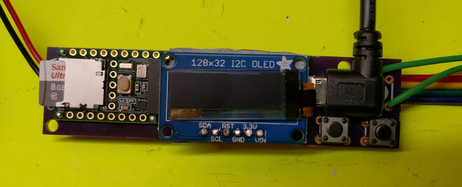
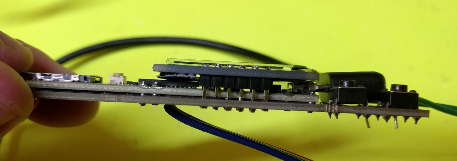
This takes in power on the left and outputs power and LED control data on the right, with control buttons and screen in the middle. Something more custom could’ve been smaller of course, but this was good enough.
Look and Feel
This is where Fusion 360 came in heavily as I used this project as an excuse to really learn how to model every component (not just the 3D printed ones). And it seriously paid off:
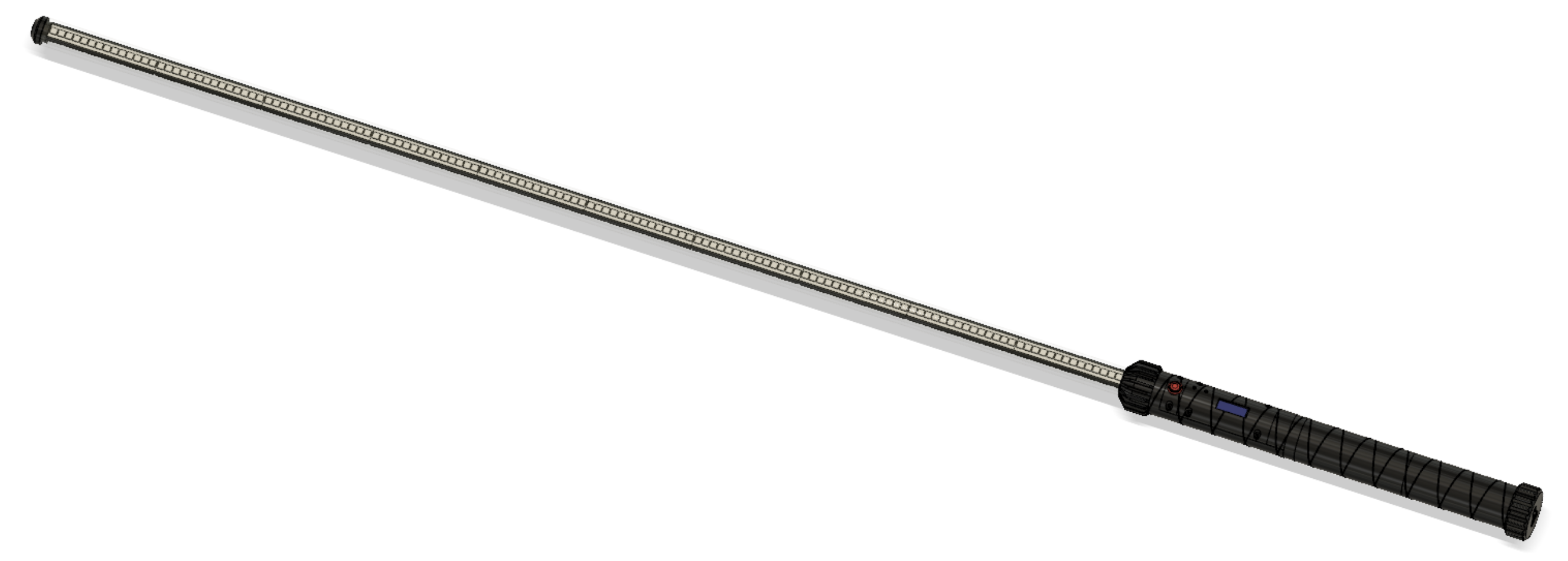
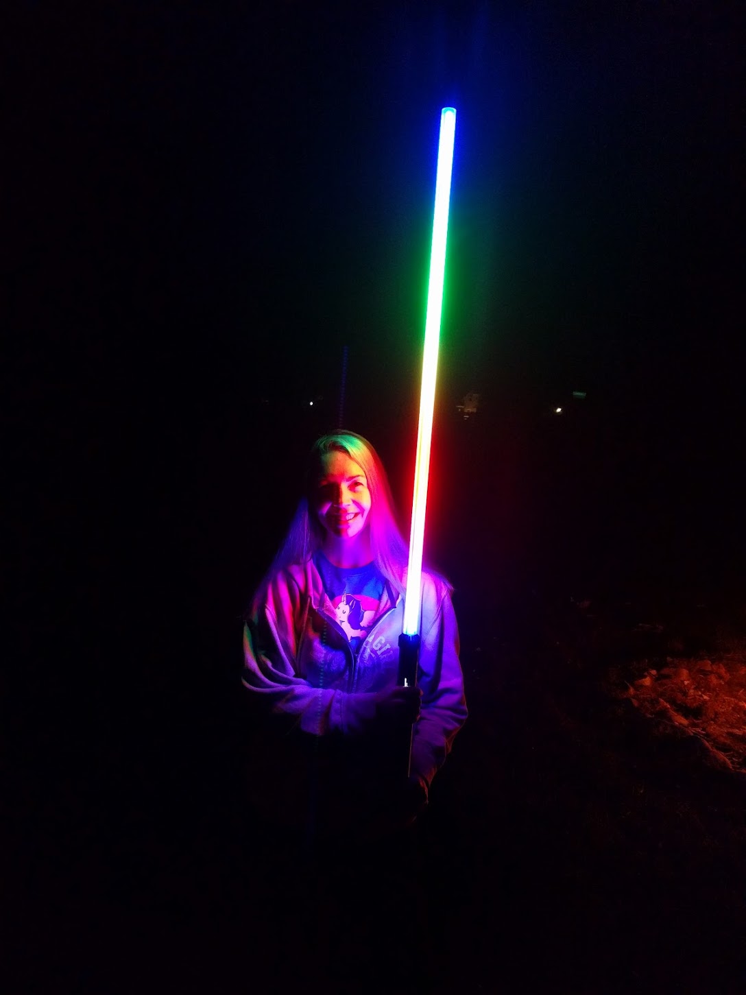
Now, as you can obviously see above, there’s nothing “Star Wars screen accurate” about this. It is a light saber in name and concept only. My designs typically lean far to the function over form side of things. Which is good, because I like that aesthetic.
The other thing you might notice is that this is less of a saber and more of a broadsword, and you’d not be wrong. When I saw those 144/m LED strips I just thought “a 1 meter blade sounds good!” without really thinking of the implications of a 1 meter long sword blade. For those of the freedom units persuasion, the entire sword is 54 inches long, with a 15 inch hilt. It’s enormous.
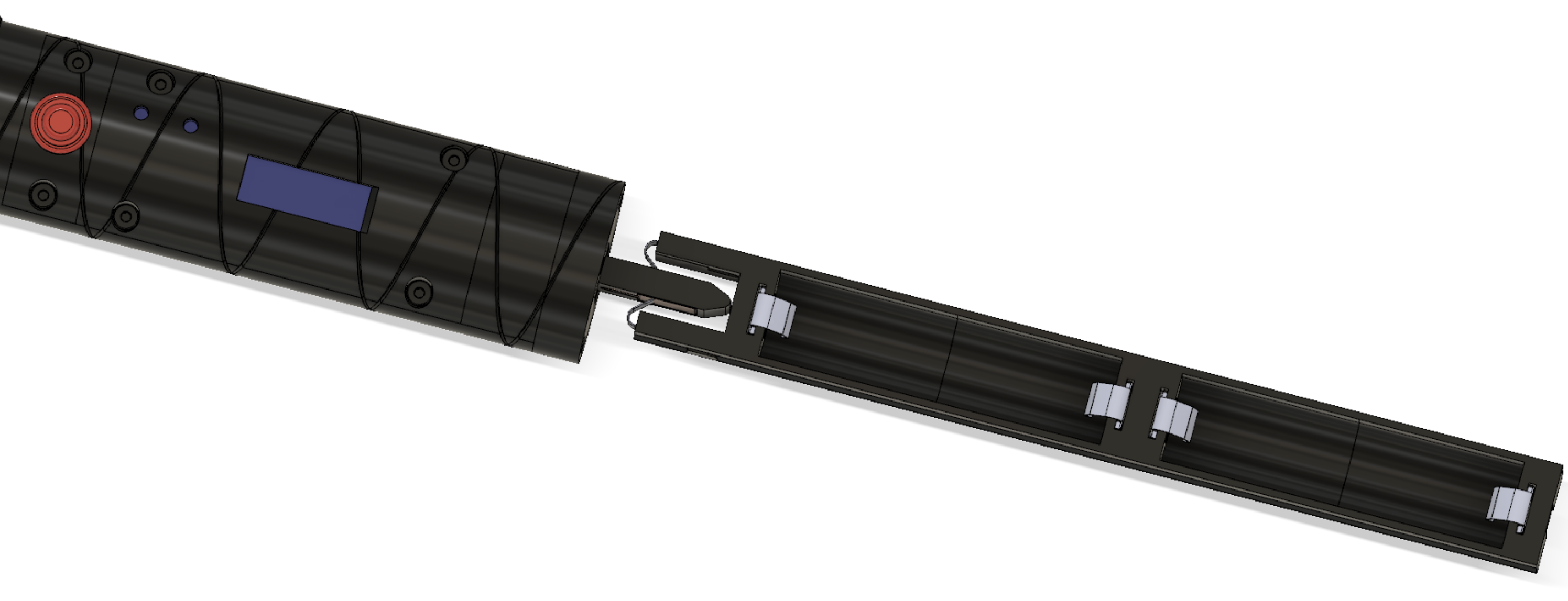
Anyways, the design is pretty basic. The hilt is all 3D printed, of course. As is the “core” of the blade. In the interest of as much of a 360 ° viewable blade as possible, there are actually 3 strips, connected in parallel, inside the blade, arranged in a triangular fashion.
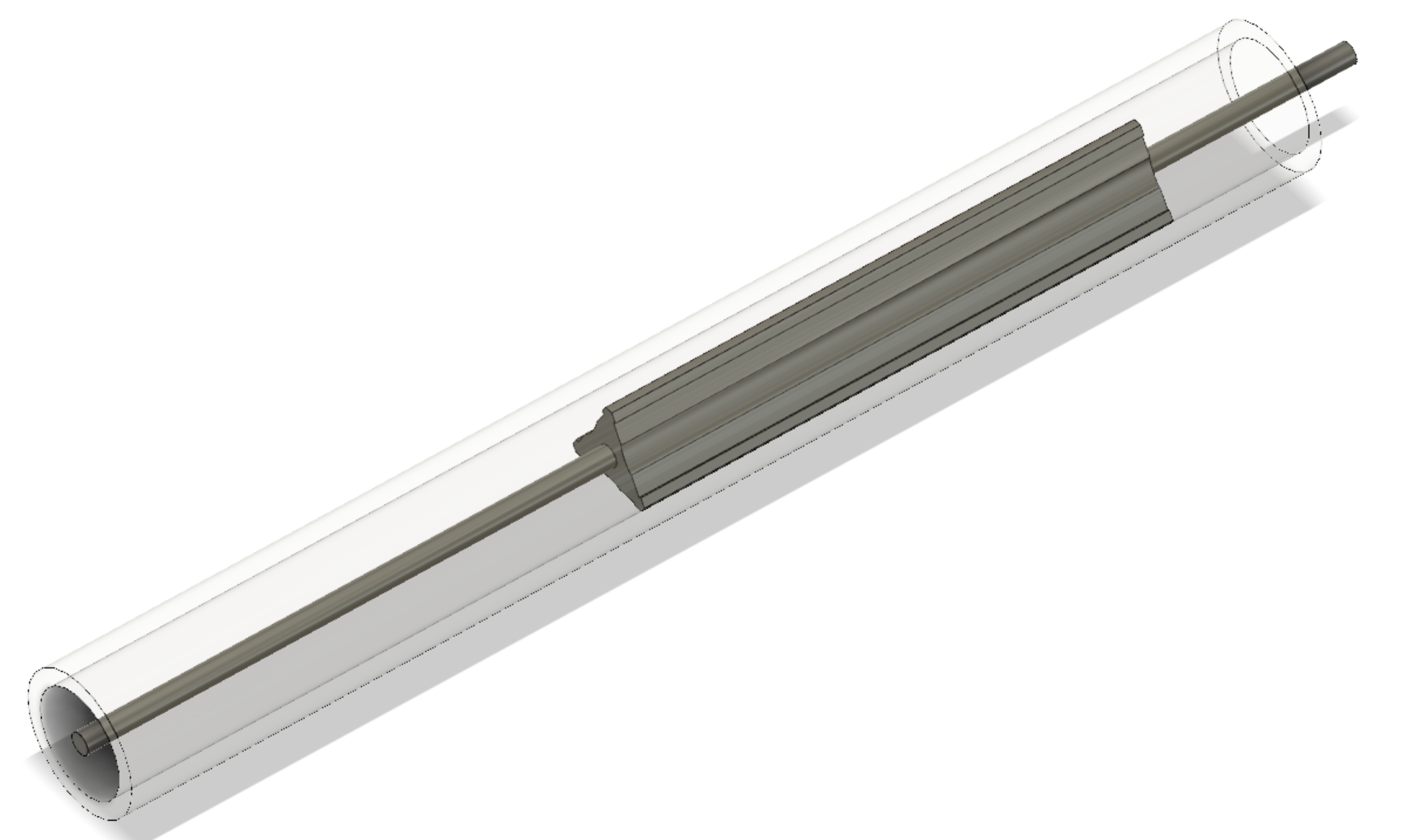
Above shows a simplified version of the actual blade assembly. It’s comprised of ten 100mm long “core” sections, which hold the strips in that triangular setup. These were all held together with a 3mm steel rod and lots of 2-part epoxy. And finally, the entire blade is encased in a 25mm OD polycarbonate tube.
My original plan with the tube was to leave it completely clear so that you could see how the blade “works”. But during initial testing I quickly decided that I didn’t like the look. Not wanting to order more tubing in a translucent white or something, I gave some sandpaper a shot:

The final blade ended up going through 100, 200, 400, and 800 grit before I was happy with the finish, but I was very happy with the result. If I did it again I’d just use translucent white, but this was fine.
To cap it all off, I kept the controls simple with a nice layout on the hilt with the screen, 2 buttons for menus and one big red button as the “activate” button.
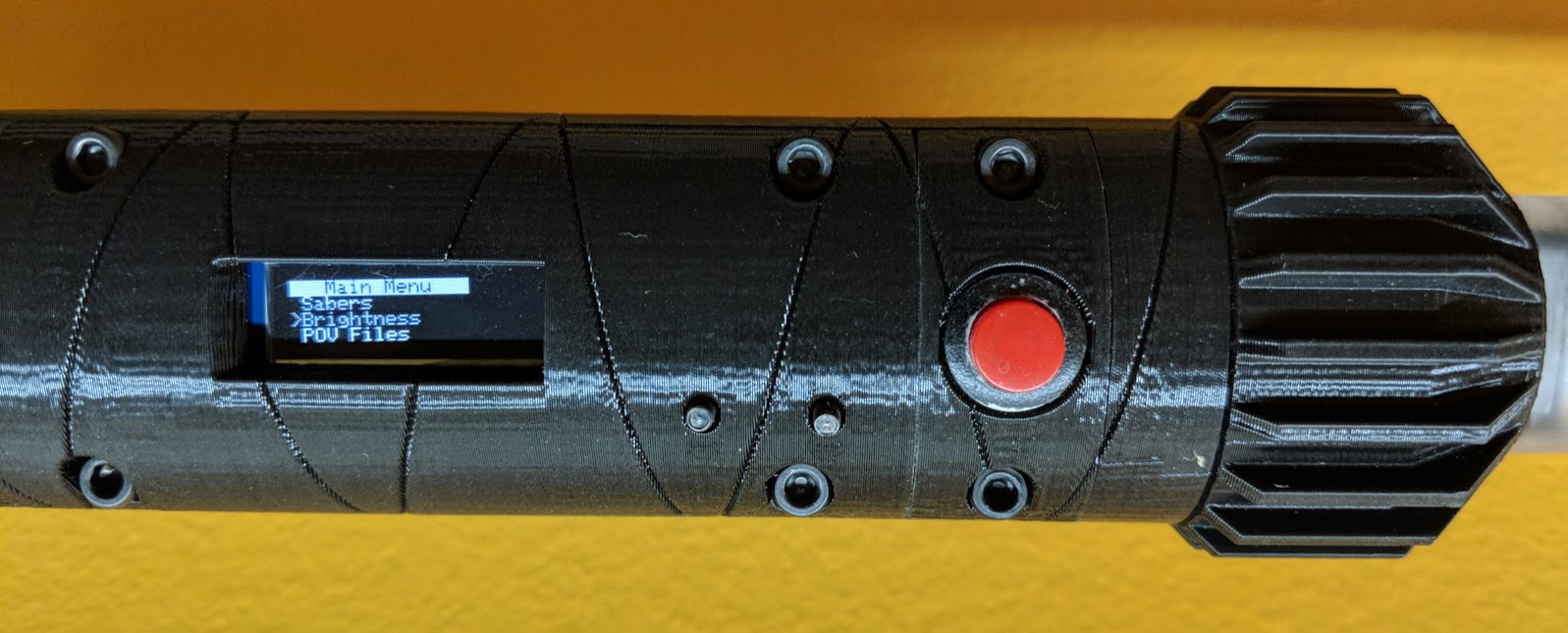
Again with the industrial / functional feel of course. Even the two menu buttons are actually just inverted screws resting atop the tactile switches. Hey, it worked ;)
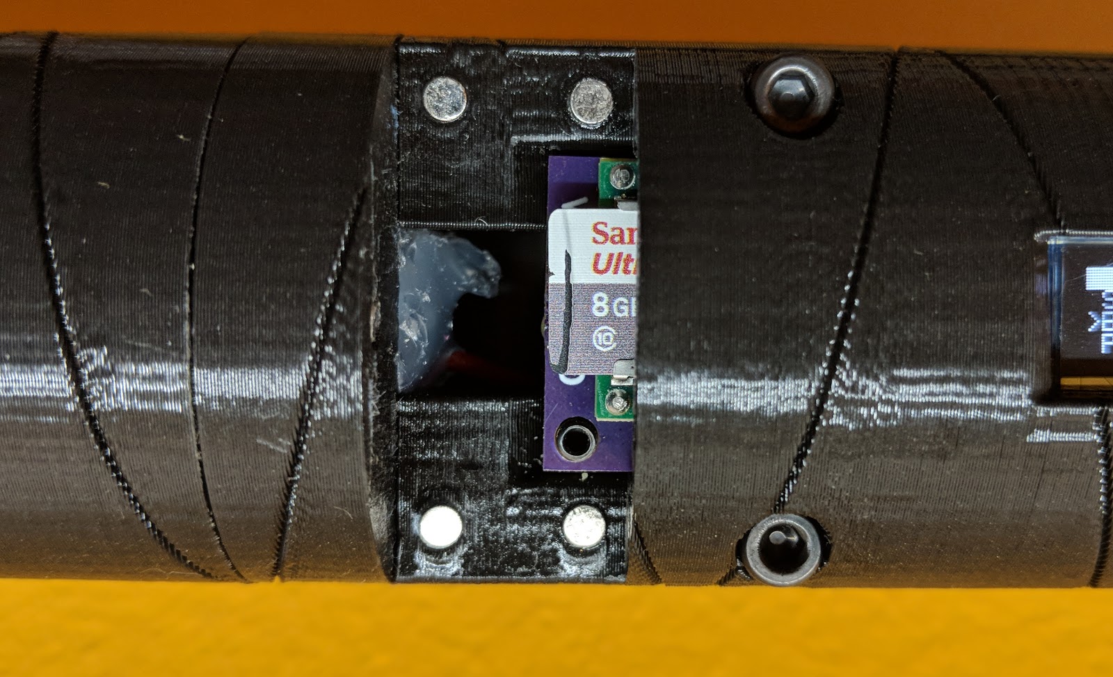
One of the more interesting design aspects I created is this nice little magnetic access door for getting to the SD card:
Power
A light saber is no good unless is portable of course, so much care had to be taken with powering this many LEDs. In theory, all these LEDs could draw nearly 20 amps at full brightness. This was in part mitigated by choice of SK9822 LEDs over WS2812 or APA102 as they include constant current brightness control. And they are so bright that I actually limited the max available brightness to merely 40% of actual. But still, that’s a lot of power.
Given the size and shape of the hilt it was quickly apparent that they venerable 18650 battery was likely the best choice. It’s not 5V like these LEDs typically run on but it ended up being a nice middle ground between the LED voltage and the Teensy voltage that I was able to run both directly off the battery with zero regulation. I technically could have run everything off a single cell but in the interest of battery life I decided to use two cells in parallel instead. The problem was how to make those cells removeable for charging… and that’s where some clever CAD work came in:
What you see above is a cut-away from the CAD model of the battery “core” and how it interfaces with the rest of the saber. The right portion is a completely removable piece that holds two 18650 cells, wired in parallel. Contact to the batteries is made via Keystone 5209 spring contacts. The clever bit is that contact of the battery pack to the saber is made with the same contacts. You can see there is a small “blade” with flat metal plates on each side at the bottom of the upper section of the hilt. This fits between the two spring contacts on the battery core, bringing power to the rest of the system.
This also allowed me to create a second power “core” that simply has a barrel jack connector so that the entire saber can be powered from a wall supply for display purposes. This was originally done for events like Maker Faire and SparkCon where it would likely sit as a display piece for hours at a time. However, it turns out that the two 18650 cells can power the whole thing for over 4 hours! Honestly, that’s about 3.5 hours longer than I expected.
Software
The firmware that runs everything is relatively simple and can be found on GitHub, of course. Aside from all the menu operations, all it really does is read 144*3 bytes at a time from files on the SD card, taking that data and sending it to the LED strip using a modified version of the awesome FastLED library. The modification was merely to support the SK9822 constant brightness control mode which has not yet made it into FastLED master.
I called the files bitmaps above, but that’s not entirely accurate. The main difference is that a bitmap includes metadata and I decided that I wanted to be lazy on the firmware side and not have to deal with any of that. So the files were generated using a simple python script which extracts the raw pixel data and writes it to a binary file. This ended up being ridiculously efficient. I was able to push up to 500 updates to the LED strip without issue… direct from the SD card. I originally had assumed I would have to buffer the entire image in memory (hence the Teensy 3.6) but the SD card interface was more than fast enough for the task.
That’s really all there was too it. I would either take existing images or generate images from BiblioPixel animations and then run them through the script mentioned above. Because I’m lazy and I didn’t include an accelerometer the speed at which each image ran was just the “file extension” of each file. So logo.90 would display our logo at a rate of 90 colums per second. If the speed needed to be changed, I simply updated the extension value.
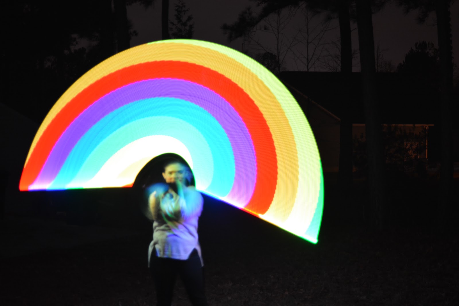
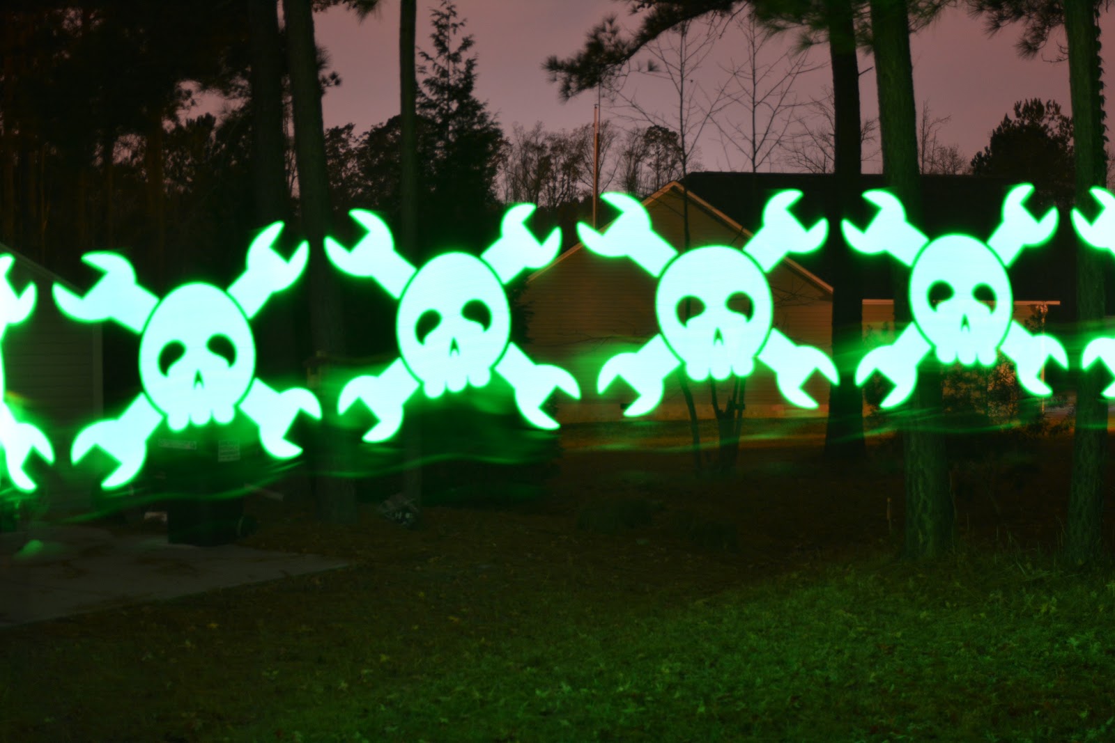
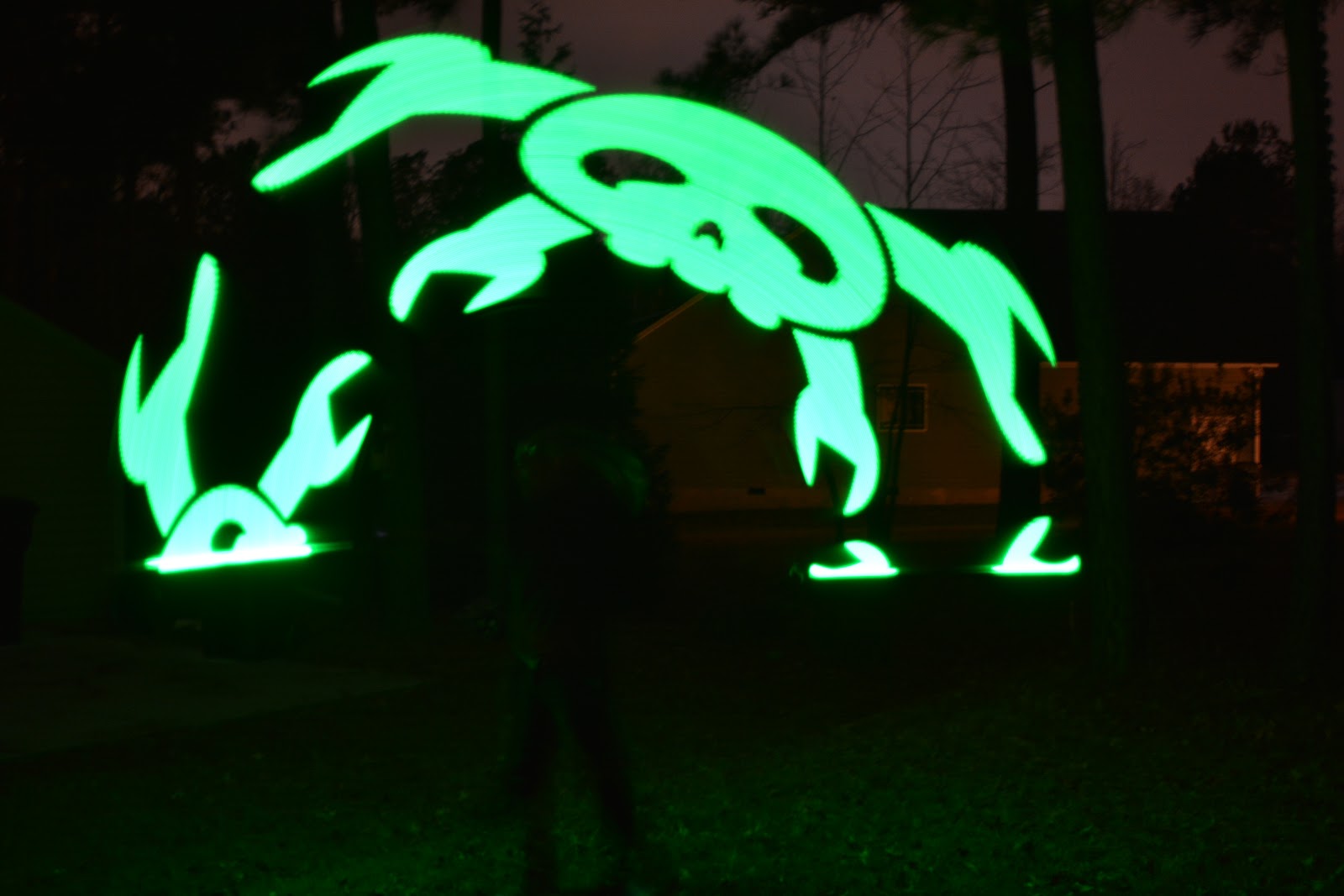
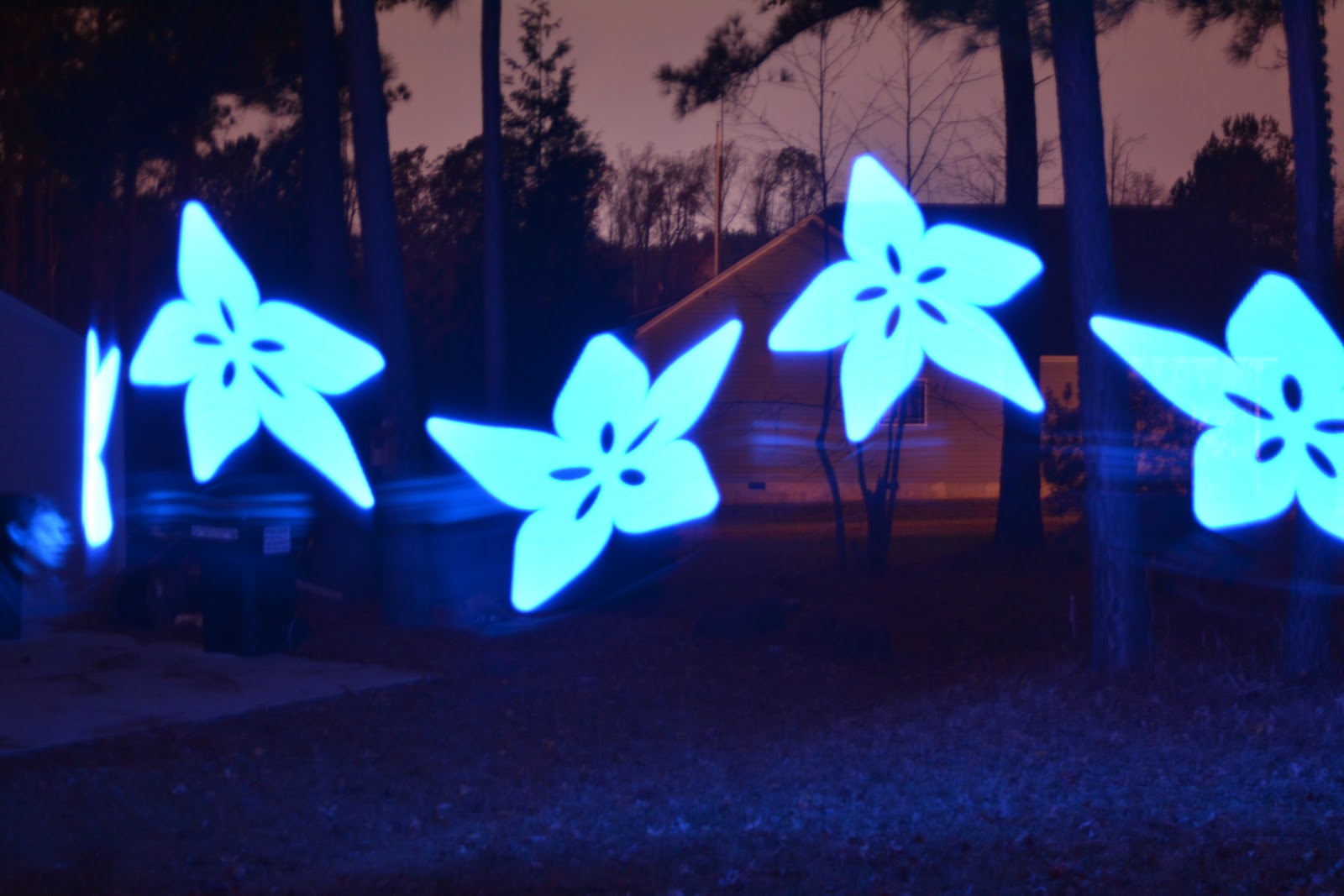
Goodies
Before I get to the good part… the gallery… be sure to check out these:
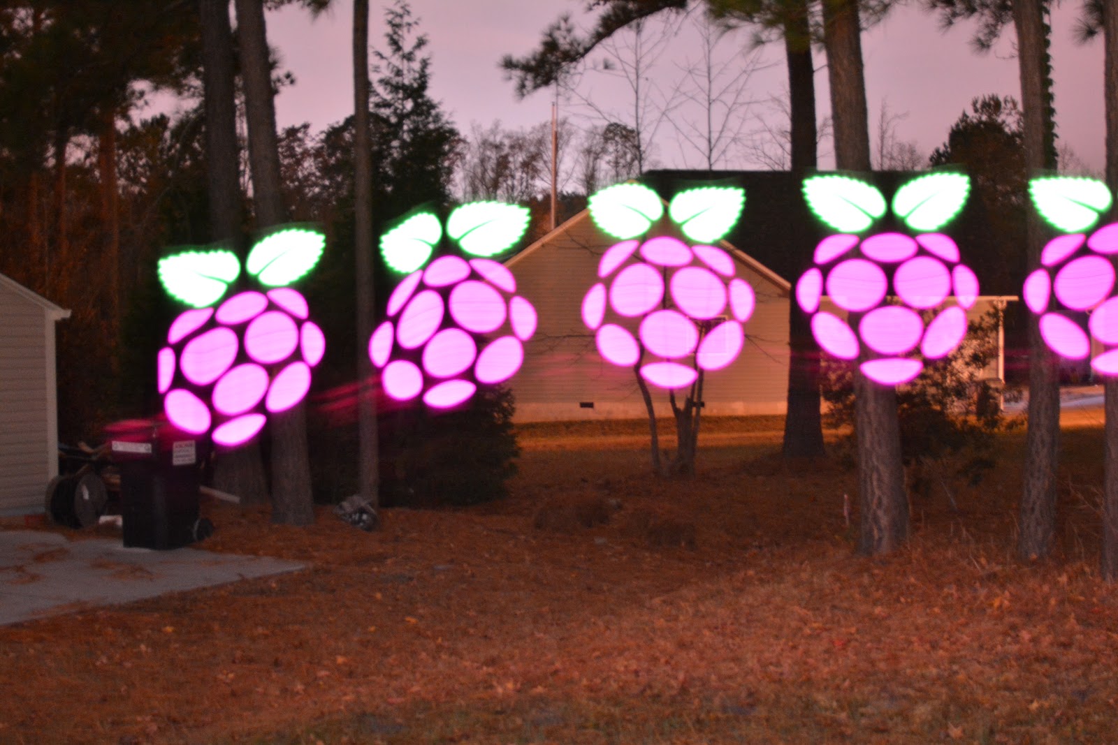
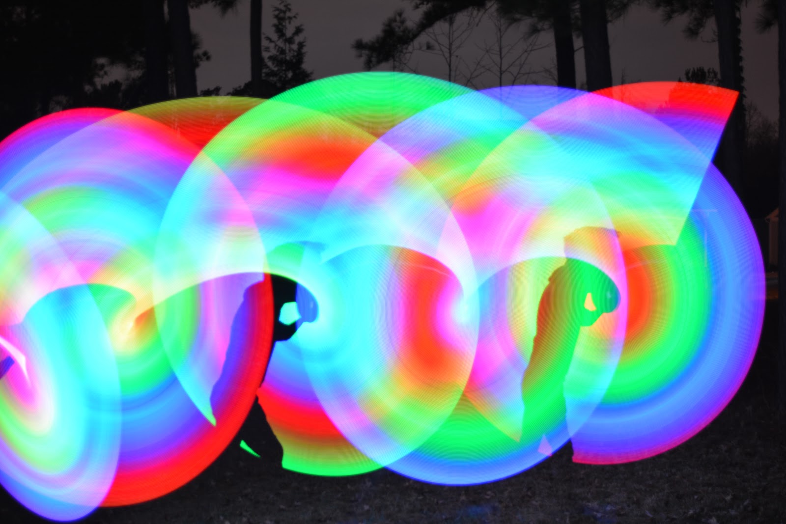
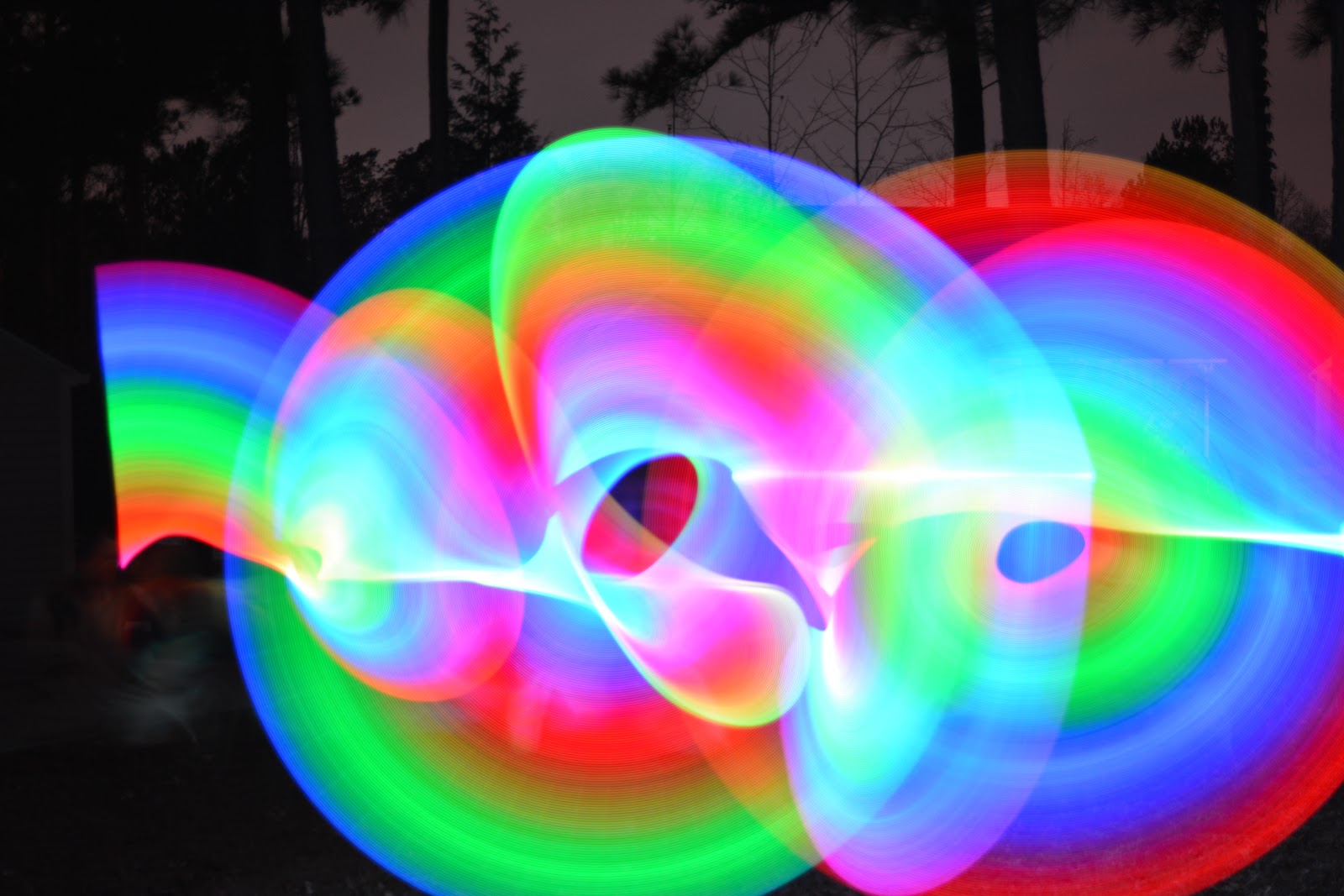
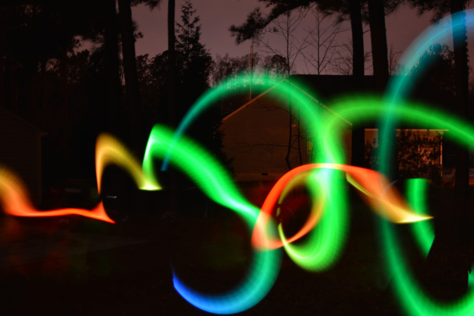
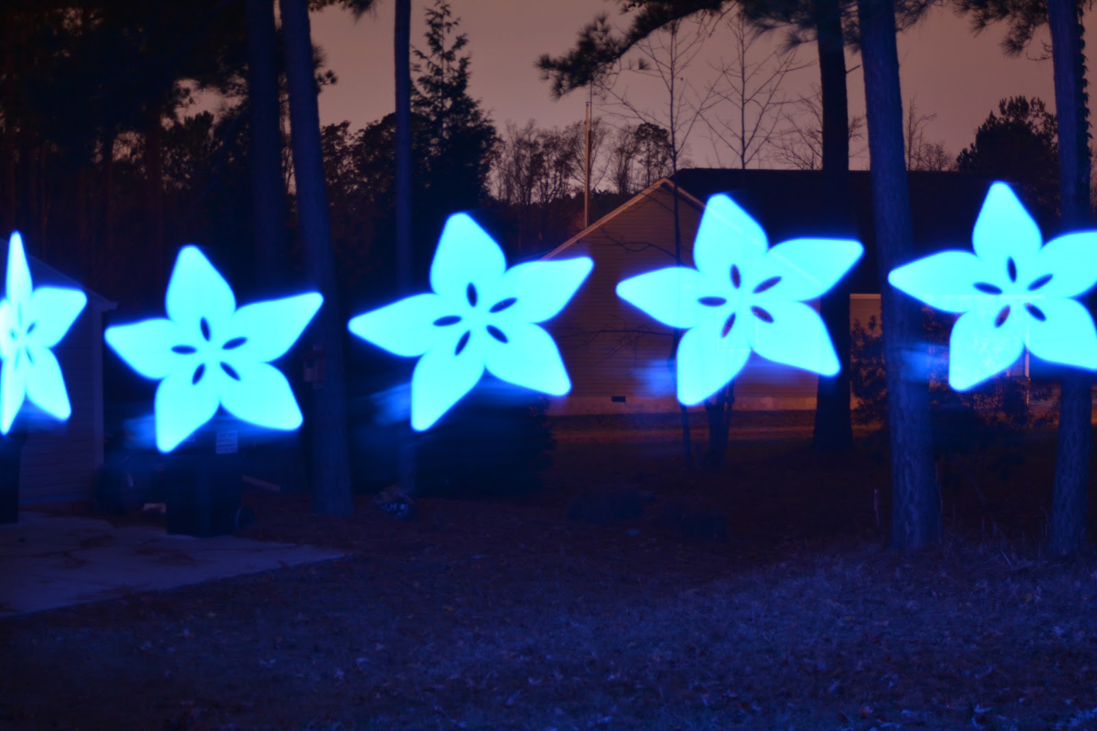
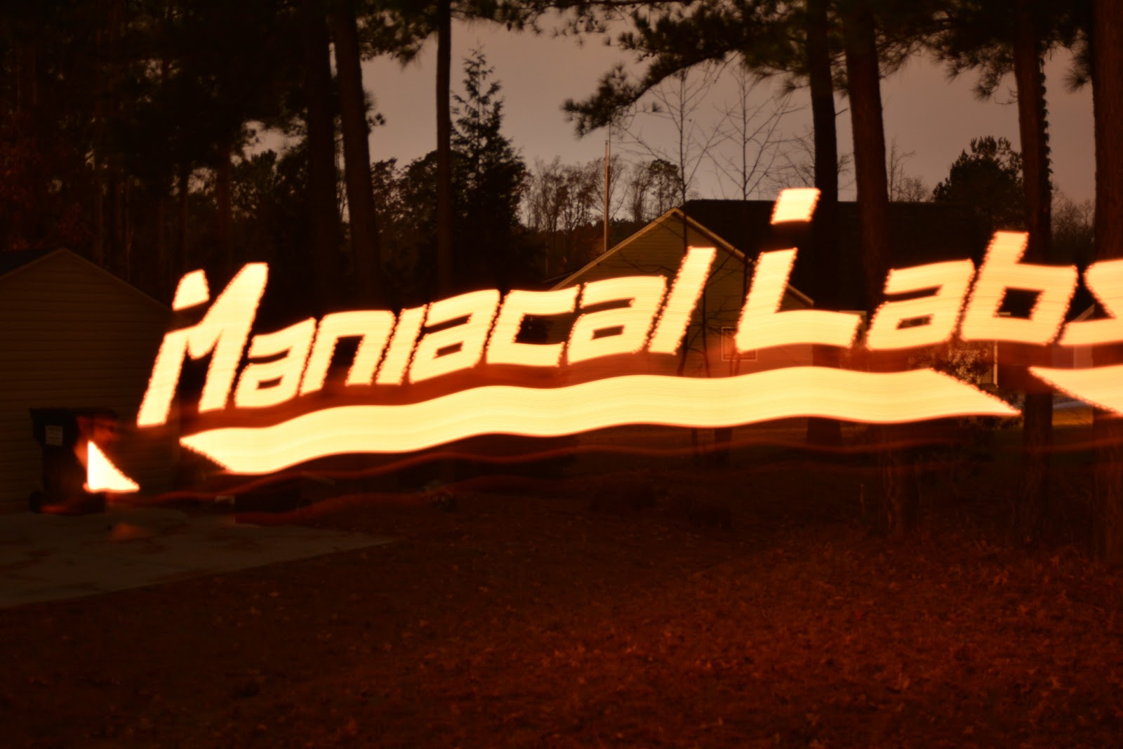
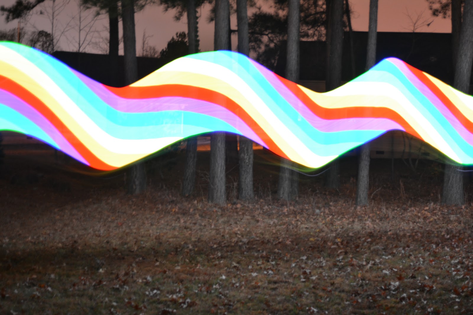
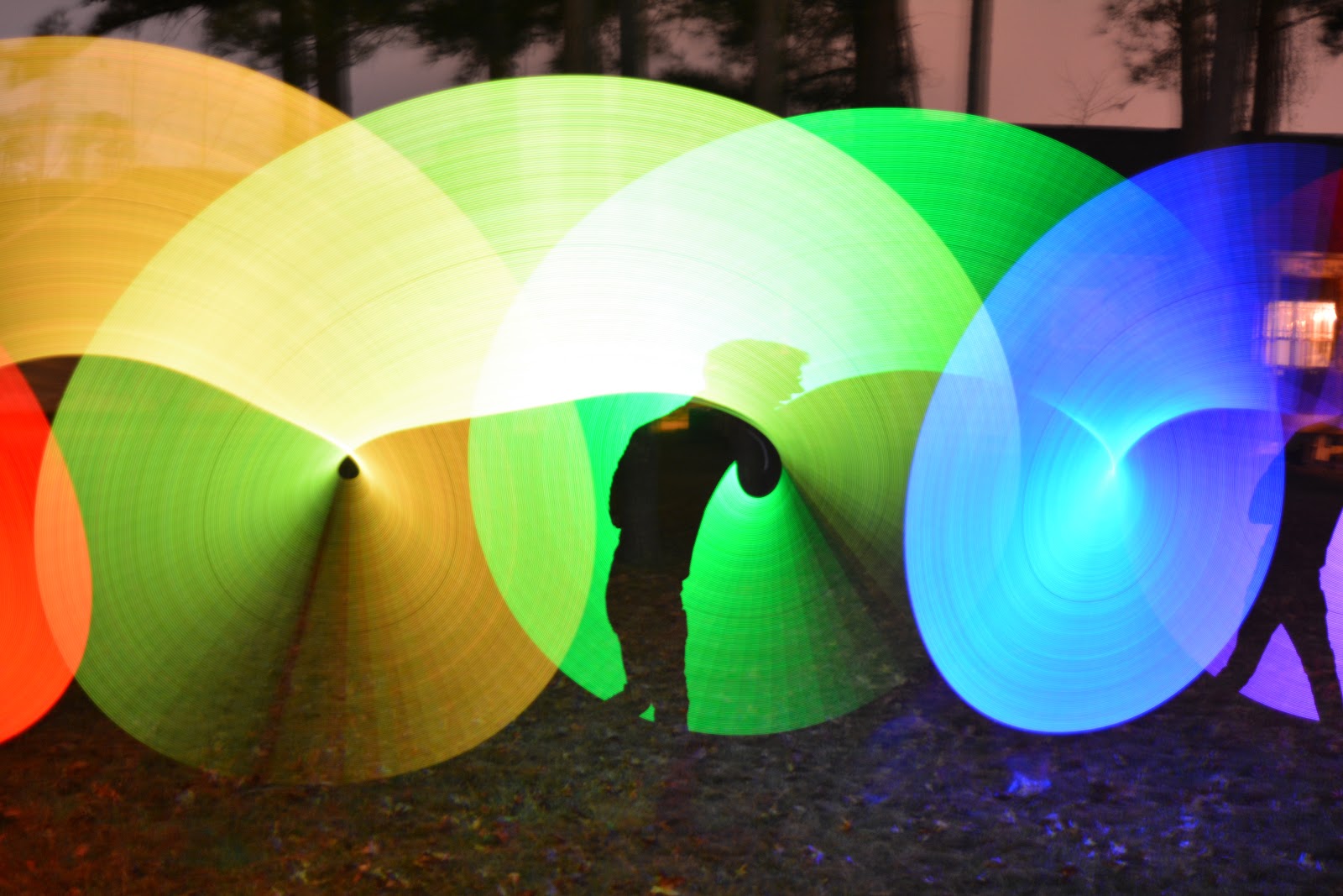
And now… The gallery. With much pandering to Raspberry Pi, HackADay, and Adafruit… What can I say, logos work well for this ;)