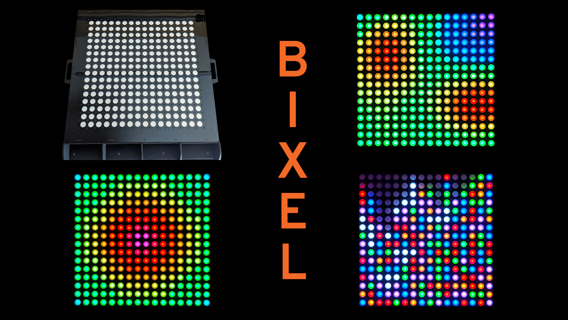
We’ve made all manner of LED displays over the years. Some simple, some complex, some tiny, some huge. But no other has been such a culmination of all the skills we’ve learned over the years. We call it the Bixel, for Button/Pixel.
Ok, so we’re bad at naming things. Moving on…
Every time we show off our work at Maker Faire or SparkCon we get great response from all the displays, but none more so than the interactive ones. There’s just something about a blinky thing you can reach out and touch that really attracts people’s attention. With that in mind, we have wanted to build an interactive display where each pixel hides a button so that people can directly touch and manipulate the pixels.
For those that are already screaming “just give me the sweet, sweet video!”, see below for a wonderful time-lapse build. Otherwise, read on!
Design
Originally the plan was to find some arcade buttons with built-in RGB LEDs as they are literally designed to do what we want. However, the cheapest we could find was more than $2 per button and for a 16x16 display that’s over $500 just for the buttons alone.
LEDs
Beyond just the cost, arcade buttons posed another problem; every one we could find simply had LED wires for Ground, Red, Green, and Blue. This meant that we would need to drive the full 16x16 array with some sort of multiplexing scheme. Not impossible, by any means, but it makes both the code and the PCB layout considerably more complicated.
Even still, we had originally assumed that multiplexing the LEDs would be the cheapest way to go. But after much research and some discussion with our LED supplier in China, we came to the realization that we could use standard digital, chainable LEDs which would simplify the code and the PCB while being far cheaper than the arcade buttons. This was even when our new plan required an enormous PCB, but more on that later.
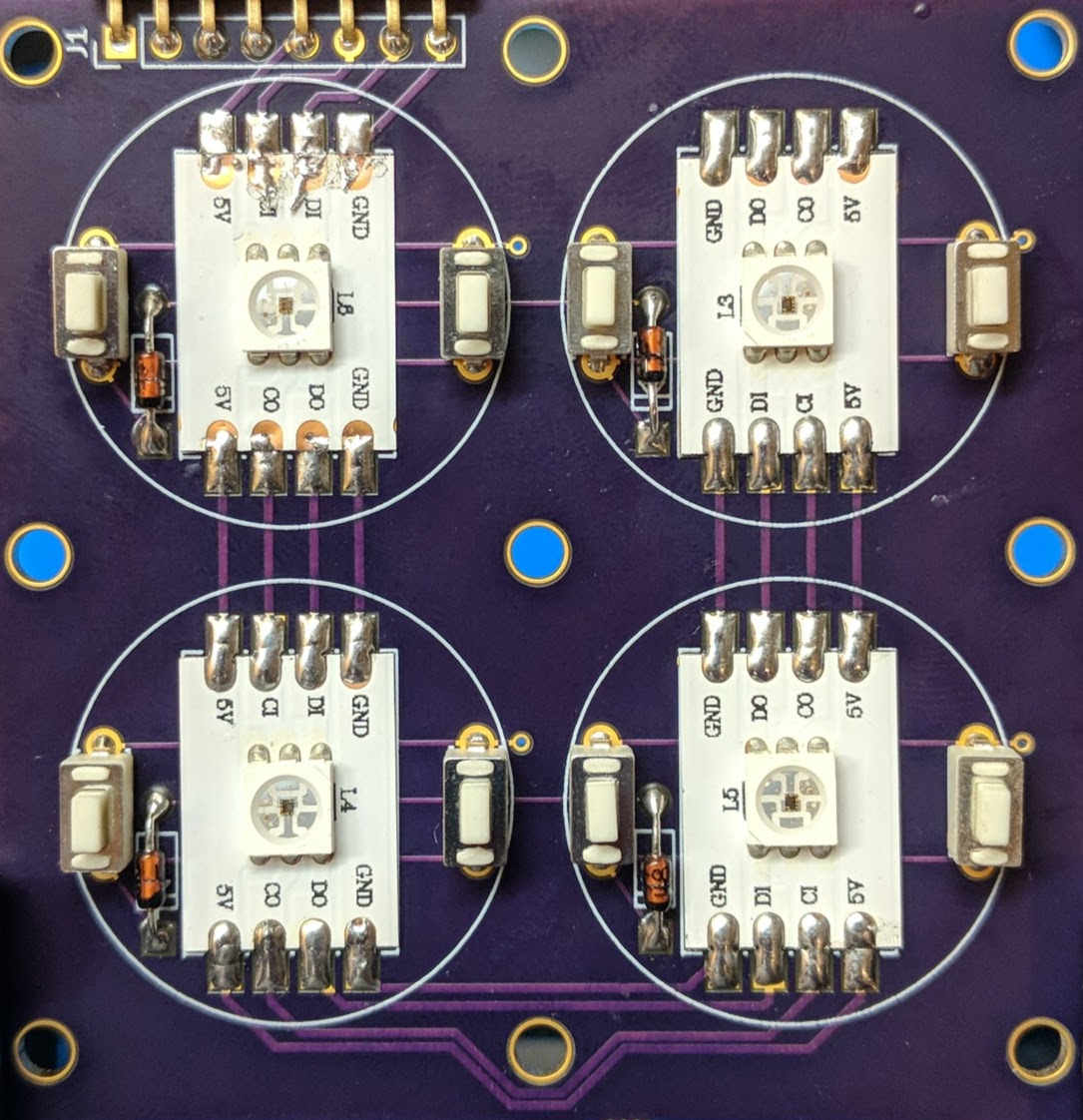
Typically something like this would just use the bare LED modules (SK9822, an APA102 clone, in our case) soldered directly to the PCB. But besides the fact that these would need to be expertly hand soldered or preferably reflow soldered to the massive PCB, we’ve had exceptionally poor luck with using these LEDs in the past. They are extremely heat and moisture sensitive and prone to failure during the soldering process. However, once soldered with the right equipment they seem bulletproof.
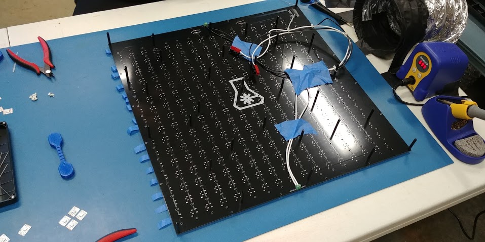
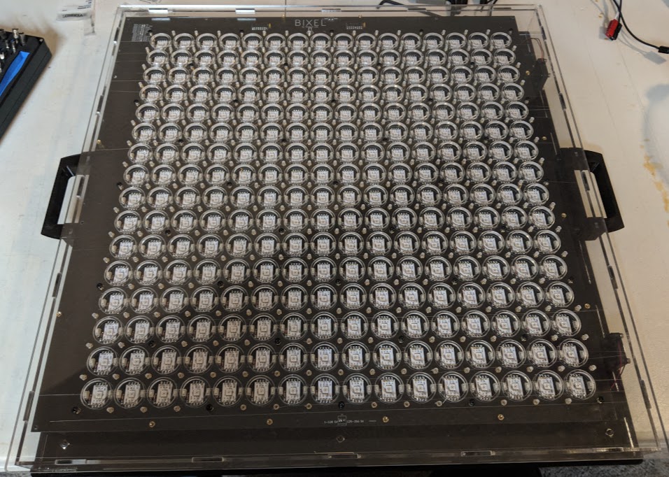
So with this in mind, we fell upon a novel solution; we would simply purchase full strips of LEDs, cut them up into the individual pixel sections, and then solder those directly to the PCB. All it took was creating a custom component footprint in KiCad. As you can see below, they turned out quite clean:
Buttons
The footprints you can see above were actually something new for us; an aggregate footprint. As in a footprint that actually contained the footprints for more than one component on the PCB. This aided greatly in the layout of the next part, the buttons.
Fortunately, this ended up being a solved problem because of the custom computer keyboard community. The task of reading multiple buttons with as few pins as possible happens right under your fingers, every time you use a computer keyboard. There was no lack of information on building your own keyboard with a microcontroller. Aside from nearly double the number of buttons, a keyboard is basically what we were trying to create. One of the best and most complete sources we found was over at OpenMusicLabs.com
Specifically, we decided to go with a parallel-out shift register setup using the common 595 chip. This allowed us to scan the entire matrix with 19 pins; 3 for the shift registers handling the columns and 16 for the rows. Technically, less pins would’ve been possible with more external ICs, but as we were already planning on using the spacious (in terms of GPIO) Teensy 3.6 to handle the matrix, we had the pins to spare.
The circuit itself was incredibly simple and all the research had basically been done leaving the last component easy to find; the 1N4148 diode. This allows what’s known as “N-Key Rollover”, or the ability to press as many keys as you would like simultaneously and read them all. That specific diode is basically the de-facto standard for the custom keyboard scene so we went with that and it works wonderfully.
PCB
At the start of the project, the thought of creating a 500x500mm (20x20 inch) PCB was absolutely insane. But thanks to cheap PCB manufacturing from China, we were able to manufacture this behemoth of a PCB for a mere $100 each!
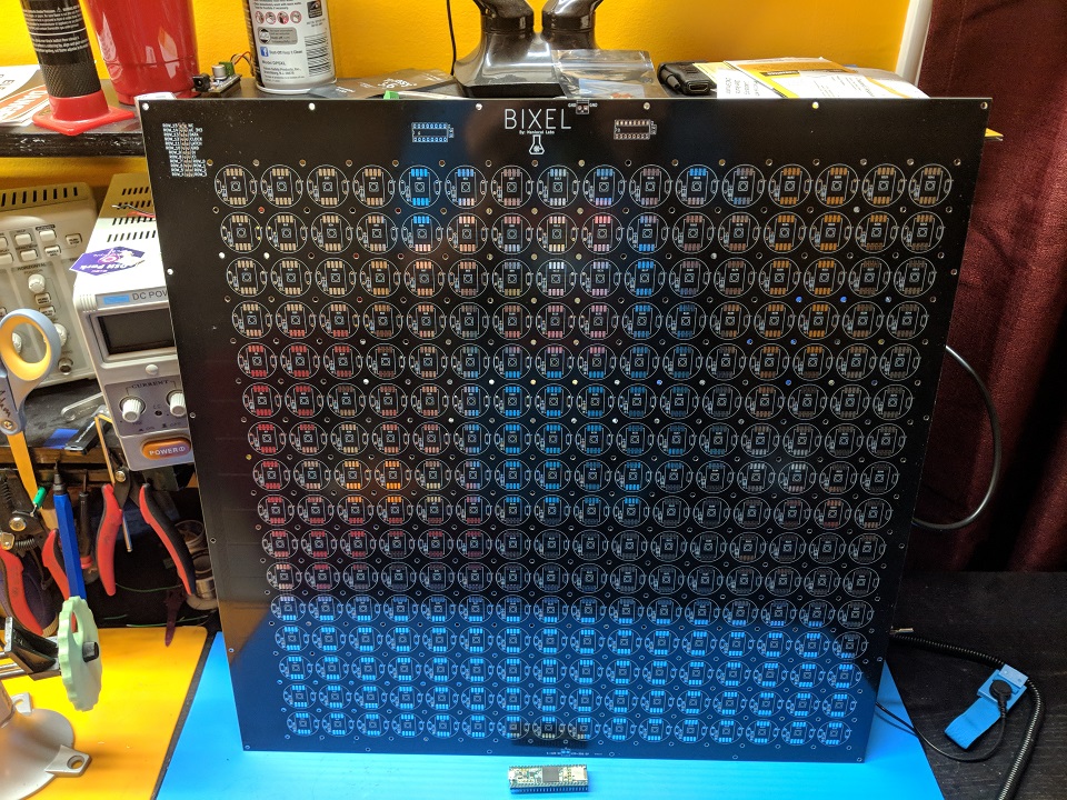
Have you ever seen a PCB that large?!
Ok, so we had to buy 5 of them as that was the minimum order, but even if we don’t use all of them that’s still a complete steal. And, come on… we’re going to build more of these :)
This monster was, of course, entirely designed in the wonderful KiCad EDA and required all the tricks in the book to keep from going insane during the layout process. The aforementioned aggregate footprint helped a great deal, but it was still quite the task.
Amazingly, we were able to do all this with a standard 2-layer PCB. A big part of that is because we went with the digital LEDs still attached to the strip. This allowed us to run the button row traces under the LEDs. All that was left after that was the button column traces which simply run in between the LED/Button columns. The most complicated part ended up fitting all the row and column traces and, as you can see above, we actually shifted the whole matrix off-center to accommodate the traces and shift registers. But then by mounting this in the case off-center in the other direction, you would never know everything isn’t perfectly centered.
To simplify the design we also opted to not include anything but the bare essentials on the main PCB, and instead move all control hardware to another PCB.
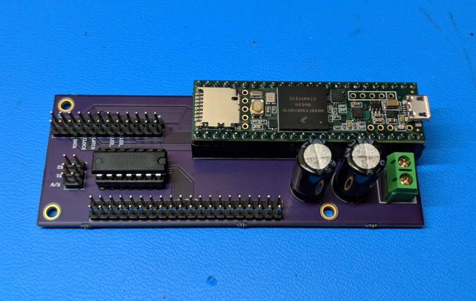
Aside from just simplifying the larger PCB this also made things a lot more flexible. The purple PCB you see above was designed after we had already ordered the main board. We were still debating the best option for controlling the whole setup, and this made it super easy to just connect everything up to whatever we finally decided on. Speaking of which…
Control
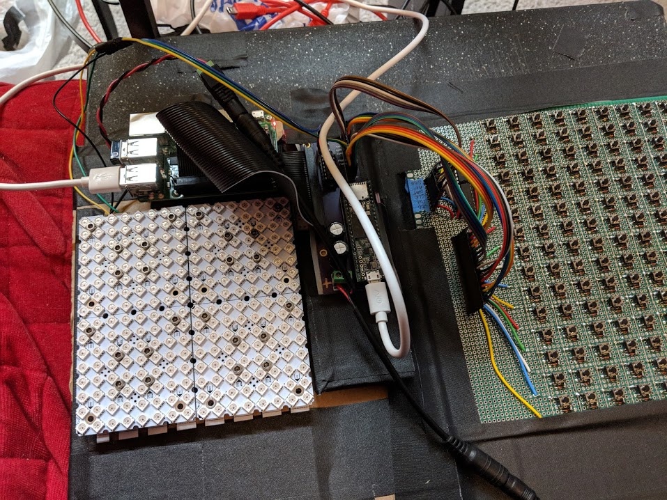
The original plan was to run absolutely everything off a Teensy 3.6 as it’s a tremendously powerful microcontroller. This would, in theory, work. But, in practice, there were some issues. Fortunately, we started with a rough prototype to test out the basic concepts:
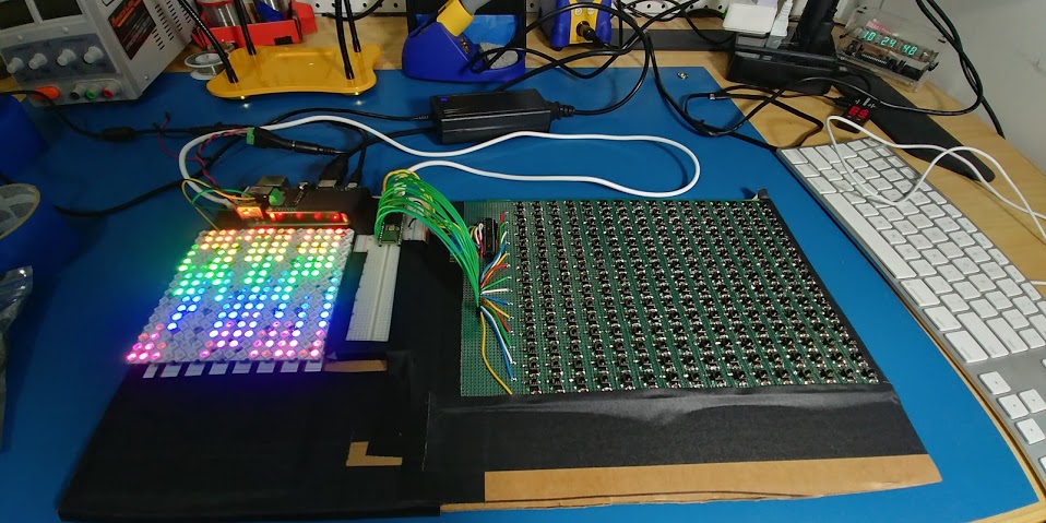
But in testing with this crazy prototype, we quickly noticed weird behavior; the buttons would eventually stop responding.
After a great deal of testing and research it came down to the fact that the button scanning was using interrupts as was the FastLED library to drive the LEDs. There was a non-zero chance that eventually two sets of interrupts would interfere with each other and cause the whole thing to fall over. And that was with even the most basic animation, never mind something more complex like an interactive game.
So the next best solution was to offload the animation and LED control to something else. Of course, the logical answer was a Raspberry Pi 3. So, instead, the Teensy simply scanned the buttons and reports their state to the Pi over a USB serial connection. Then, we can run python code on the Pi to talk to the Teensy, run the animations, and drive the LEDs directly over the SPI output.
Normally, our own BiblioPixel would’ve been used to run everything. But, in this case, we wanted to simplify things as much as possible. So, with liberal borrowing of code from BiblioPixel, we instead created a custom, simplified, and bespoke framework to drive the system. Surely some of tricks we found along the way will make it back into BiblioPixel at some point.
The new framework breaks each of the games/animations down into classes similar to how BiblioPixel handles animation classes. But the framework automatically handles all of the button polling outside of the frame rendering and simply passes along the button data for each frame. The framerate is also fixed at 30 as that was about as fast as we could reliably scan the buttons. So we were left with a nice 1 frame per full button matrix scan relationship.
Bringing It Together
At the genesis of this project, the plan was to 3D print the whole assembly. It would’ve been… tedious. But hey, it’s what we had.
But then, this past spring, our good friend Justin of WyoLum offered us this amazing piece of equipment:
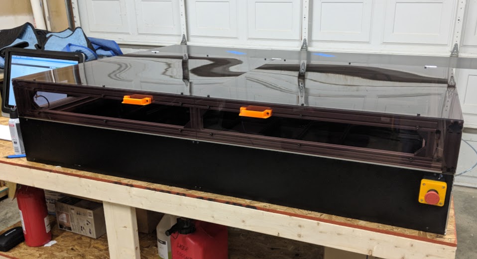
Yep, that is the amazing open source LaserSaur - a 100W CO2 laser cutter with a 1200mm x 600mm (48in x 24in) working area. We are certainly fans of “the right tool for the job” and this… this was it. So, with the proper tool in hand (or, on a giant custom table) it was off to Fusion 360 to design a case (another “right tool”).
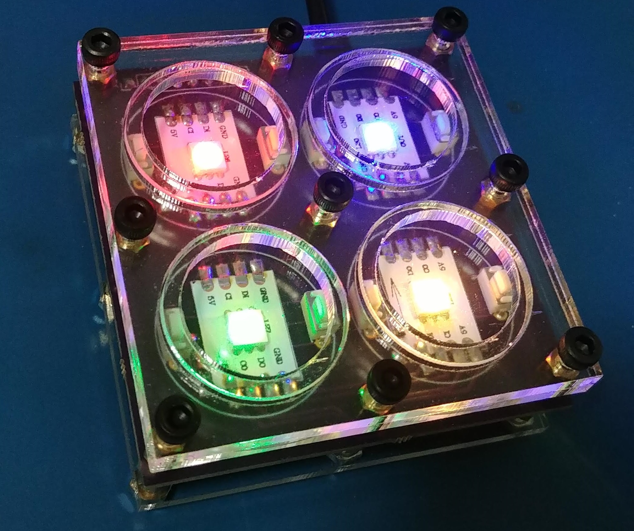
As noted above, this design was all about keeping the cost per button low. So we came up with a nifty little cheat to turn small, cheap tactile switches into large buttons. The reason we used two tactile switches is because they are then able to support a circle of 3mm acrylic, but that circle needs to be kept in the right place. The tactile switches are 5mm tall, so we used 5mm brass standoffs to elevate two 3mm thick acrylic sheets above the PCB.
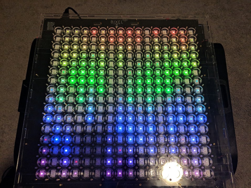
The acrylic sheet closest to the PCB has 25mm holes and the top sheet has only 20mm holes. This allowed us to hold semi-transparent white acrylic circles directly above the buttons and able to move up and down, pressing the switches, but not side to side or fall out. You can see how this all works with this mini clear prototype we made:
Much to even our surprise, this works perfectly. First time, first design and it’s perfect. Try as we might there’s no way to press the acrylic button without at least one of the tactile switches registering the press. So now we just had to scale it up!
The rest was many hours of CAD modeling of every component (gotta love the McMaster Carr import!) and after much work, we wound up with this:
With that done, we were ready to start cutting, but good acrylic is expensive so we started with some cheap clear acrylic we picked up at the local Scrap Exchange. Using clear acrylic was kind of a happy accident as it worked well to really get a feel for how everything was fitting and make a few small adjustments.
Now, we just needed to bring everything together!
Assembly
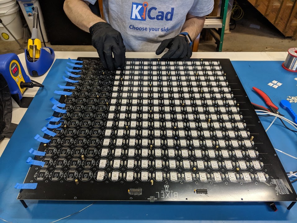
So Much Soldering
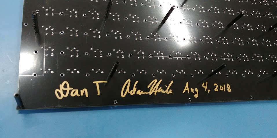
Even if we had gone with completely surface mount components, any sort of automated assembly was never really considered. For a one-off board of this size, our experience said that it would be far too expensive. This meant that we would have to suck it up and solder the entire thing by hand. This was a tremendous amount of work that we managed to knock out over a very long 11 hour day between the both of us. It was tedious work but, due to a well thought out design, not really all that difficult. The video above includes a protracted version of the time-lapse of this whole process, but if time-lapses are your thing, checkout the full version here.
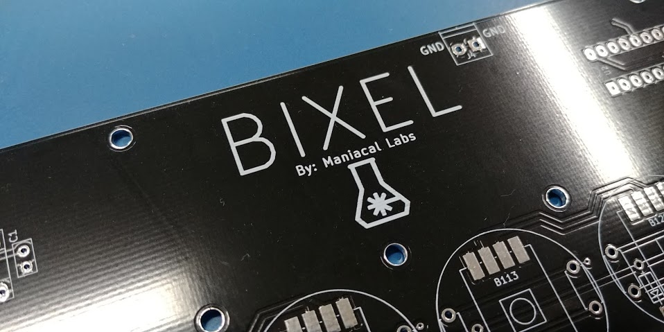
Given how much work this was, we felt it was only right to sign our work:
Pew Pew!

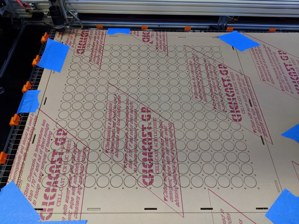
High quality acrylic in hand (the good stuff is so worth it), we set about firing the laser. As you might imagine with a design like this, it was slow going. The design isn’t complicated, it’s just (as is the theme of this project) tedious. We went slow and took our time getting everything perfectly setup for best success. After a couple evenings of cutting we had all the parts necessary.
While not likely a complete necessity, we decided to go ahead and secure the case sides to the bottom with acrylic cement. Though we made sure to make the tolerances as small as possible, this greatly helped close the gaps and increase the case rigidity as acrylic cement is a chemical solvent that permanently bonds the parts together.
Adam chooses to simply ignore the part where he glued the bottom on backwards and had to cut more…
Hardware
Again with the tedium, to do this right the design includes:
- 289 5mm M3 standoffs
- 249 M3 nuts
- 50 35mm M3 standoffs
- 339 8mm M3 screws
The 5mm standoffs hold up the top acrylic plates as mentioned before and the 35mm standoffs provide spacing to mount all the control and power components underneath the PCB.
We originally just bolted everything together and tightened things as much as felt comfortable, but upon trying to dismantle the clear test case we quickly found that some of the standoffs were coming loose, making it nearly impossible to completely undo the 8mm screws holding the top and bottom parts of the case together. This was solved with a combination of Loctite thread locker and super glue. After that, all the hardware stayed nicely in place.
Electronics
The electronics are really not all that complex and include:
- Raspberry Pi 3B+
- Teensy 3.6
- Panel mount USB port (for accessing the Pi USB)
- 2x 24mm arcade buttons (for brightness and menu)
- 2x rocker switches (power and read-only control)
- C14 power plug socket
- 2x 30x30mm 5V fan
- Meanwell LRS-100-5 90 watt power supply
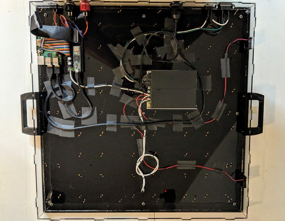
Mounting holes for everything were included right in the bottom of the case, and after copious amounts of gaffer tape cable management, we were able to get everything cleanly installed. In the picture below, you can see gold sharpie marks at various holes. This was from the first test case we made and figured out exactly where all the 35mm standoffs would end up. Therefore these marks made it easy to ensure that none of the cables would get in the way.
Were we to redesign this, we might include holes for looping zip ties around the cable or something. But for a first version, we are still quite happy with how this worked out.
All of what you see above connects to the main PCB via four power wires (the PCB is powered in halves) and a single 24 pin ribbon cable that can be seen in the top left corner.
Capping It Off
All that’s left is to bring everything together. We first placed the PCB in the bottom of the case (with all the hardware pre-installed) and secured it with a handful of screws. Then, the first top acrylic sheet was slotted onto the side panel tabs. Then came yet another tedium of inserting all the translucent white acrylic circles that act as the buttons.
The original design calls for simply placing the top black acrylic sheet on top at this point, but in doing so, we realized that at this large of a scale, there was some flex in the system. This flex meant that sometimes tightening the top screws caused the acrylic circles to push down on the tactile switches and make that button permanently pressed. We thought about several potential changes that generally included slightly thinner or thicker acrylic to be used, but 3mm is kind of a standard and the sizes we wanted just didn’t exist. So in the interest of expediency, we fell to the plan of cutting a new middle sheet out of some 0.5mm mylar we already had on hand for making stencils. This ended up being just thick enough to add the extra tolerance needed.
So with the new middle sheet, on goes the top… and all 289 screws. Hooray for tedium!
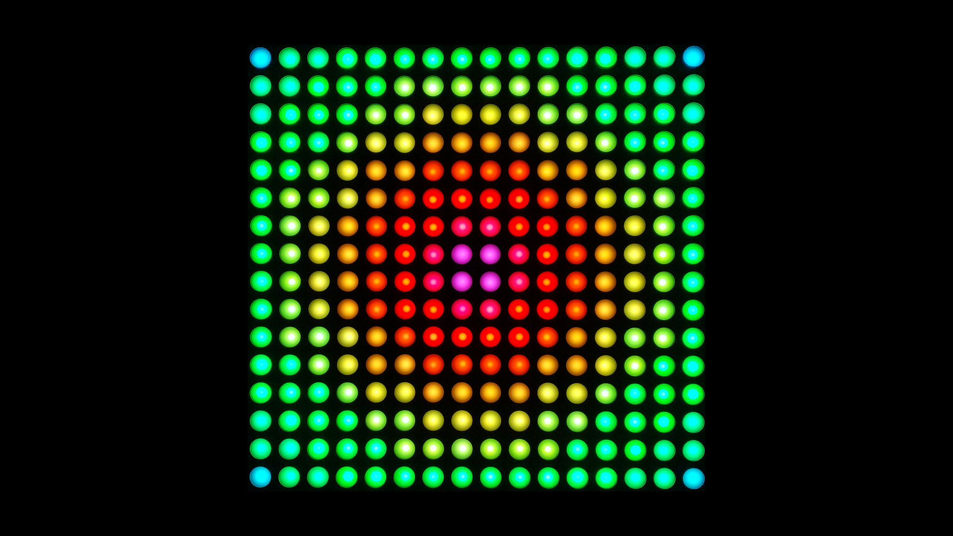
And we’ve gotta say, it turned out great!
Software
As mentioned above, everything is controlled by a custom Python framework that handles animations, buttons, and driving the LEDs. In previous projects we’ve setup all sorts of flashy web-based remote controls for our displays. These seem great, but in a situation like a Maker Faire or SparkCon, it means extra networking infrastructure is required. At the 2017 SparkCon, we had a huge number of displays, and it took nearly 2 hours just to get the network setup and all the displays connected.
So, we’ve finally learned. The Bixel employs a very simple control scheme: 2 buttons.
One button cycles through brightness levels and the other enters a stupidly simple menu mode. The menu literally consists of one button lit up for each available game or animation. Press the button and it loads that option. Sure, there’s no direct indication other than position and color, but sometimes simple is better.
To top it all off, we used a basic systemd service that quickly starts up the whole framework shortly after boot.
Avoiding Oops
The other thing we’ve learned with the many Raspberry Pi displays we’ve made is that full Linux systems really hate being powered off without warning. Too many times we’ve had a display stop working because the SD card got corrupted by an unintentional shutdown. Fortunately, the work of many smart Raspberry Pi hackers came to the rescue with this brilliant Read Only Raspberry Pi script.
This great little hack configures the Pi to be completely read only everywhere except the /tmp directory, which is redirected to RAM. This could be problematic for software that needs to write somewhere other than /tmp, but the Bixel framework never needs to write anything.
We did however want to make sure that updates to the code could be made, if necessary, and fortunately this hack can take care of that too. One of the rocker switches listed above connects between GPIO 21 and ground. If the switch is closed, shorting GPIO 21 to ground, at boot time the Pi will boot into a normal mode that allows writing. So, most of the time we leave this switch off and the Bixel can be power-cycled without fear. But simply flip that switch, cycle power, and now we can edit all we want.
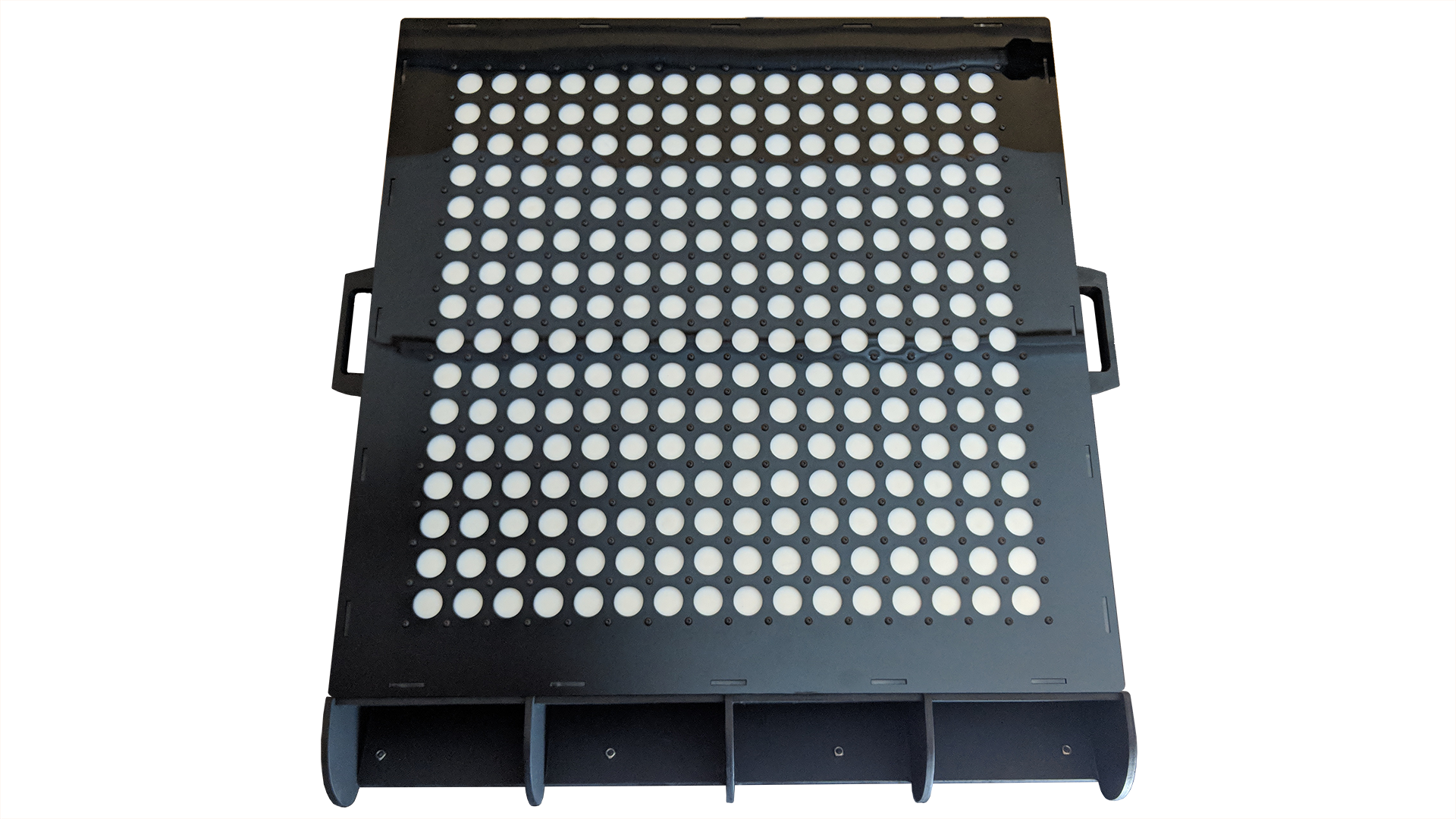
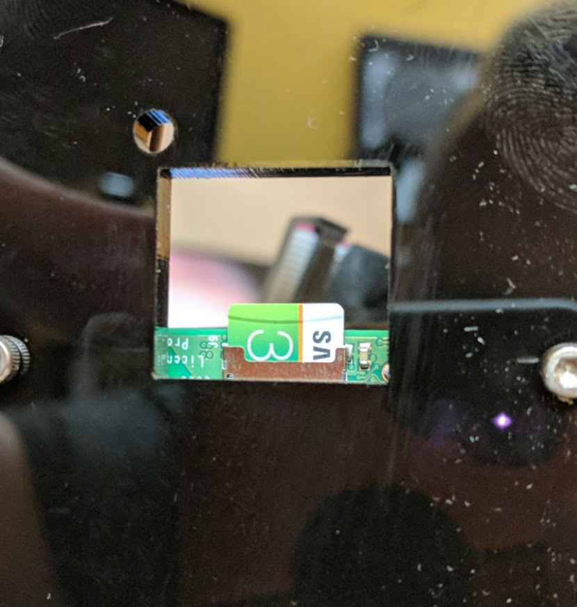
That being said, it never hurts to include a backup access hatch for the SD card ;)
Open Source
Now that you’ve made it this far, here’s the good stuff. As with everything we do, this project is 100% open source.
You can find all the firmware, python framework, and PCB files here:
https://github.com/ManiacalLabs/Bixel
And for the full CAD model from which we cut the case and planned the layout, checkout the Fusion 360 project here:
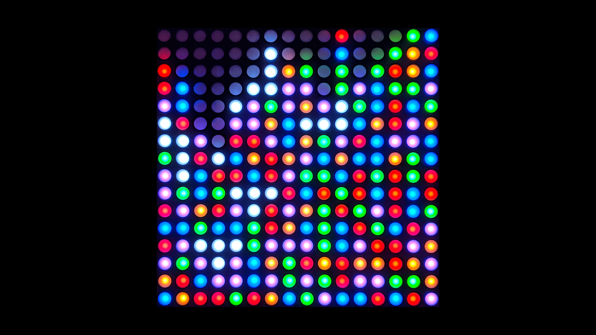
Pretty Pictures
As reward for making it this far, here’s a gallery from various stages of this project. Thanks for reading!