Jumbo1K: 32x32 LED Networked Display
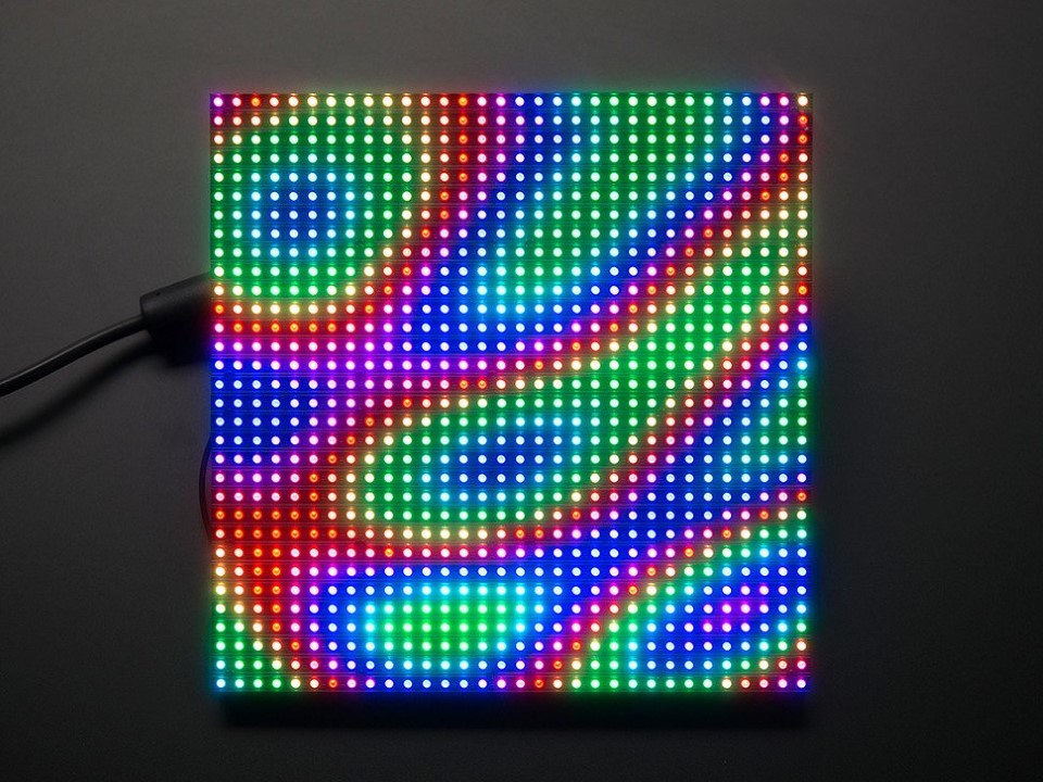
Over two years ago, I bought this awesome display panel:
It’s a 7.5” square, 32x32 resolution, 6mm LED spacing, panel that would normally be used for digital signage. Though it is a “dumb” display that requires CPU intensive multiplexing (it’s supposed to be driven by an FPGA or ASIC), with the right tools it can be way easier to use than building, ahem, other types of displays ;) I have covered this exact panel a few other times, but after a couple years of sitting in my LED storage it was time to finally make it something awesome.
To jump straight to the good stuff, check out the build video below, or continue on after the break for the full details.
Case
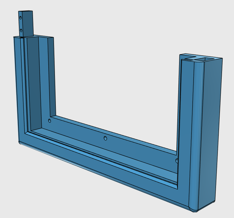
The core of this particular display is, in a way, the case. Ever LED display I’ve made up to this point has used digital LED strips or strings, which are great but also not meant for particularly high pixel density. This makes even low resolution displays pretty large, and as such, I’ve usually resorted to constructing the structure of the displays out of wood. But at only 7.5” square, with pixels only 6mm apart, it was just the right size to design a 3D printed case that would be printable within the build volume of our MakerBot Replicator 2. Almost, anyways… each half had to be separated into two parts that slot together and are secured with screws, so this made a great excuse to also learn how to design multi piece printed parts.
The front of the case is, as mentioned, printed in to halves which are identical and fit together when rotated 180 degrees to one another. There is both an opening and mount screw holes for the panel itself, as well as a slot into which the 8” square frosted acrylic slides. It’s actually designed such that the only way to get the acrylic in is with the case front in two halves, so the design limitation worked out nicely in this case as it holds the acrylic in with nothing more than the slot itself.
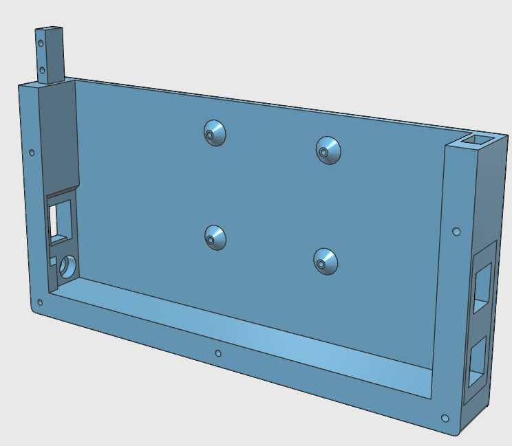
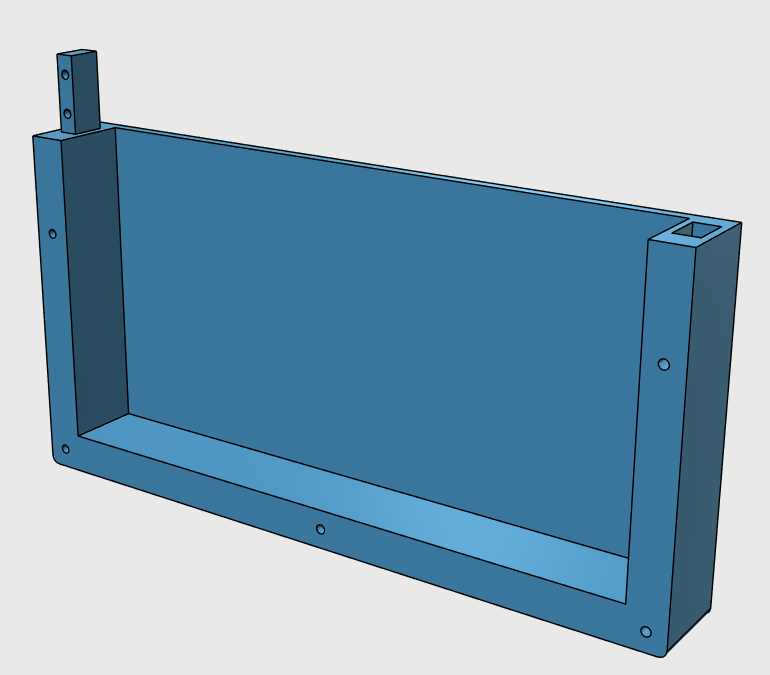
The back of the case is not in identical halves as the bottom holds not only all of the connection ports but the Raspberry Pi 3 that drives the whole thing. The top, however, is entirely plain and merely exists to round out the back and cover everything. But like the front the back pieces have the same rotational symmetry that allows them to fit together.
The front and back then screw together using ten M3x30mm screws that thread all the way through the back and into the front. Speaking of screws, for the sake of simplicity the case is also designed such that all fastening screws and completely self threading. This is achieved by making the screw hole slightly smaller than the threads. For example, for an M3 screw I typically make a 2.7-2.9mm hole. Smaller if the hole will be printed horizontally and larger if vertically. This is because on printers like the Rep2, the dimensional accuracy in the X/Y planes (parallel to the plate) is not as good as the Z-axis accuracy. In fact, it’s affected by the Z-axis layer height with the smaller the layer height, the more dimensionally accurate it will be on the X/Y plane. Just be sure to take this into account when designing. The point here is that this allows adding no extra hardware and not needing a nut on the other side of each hole. The downside is the durability of the hole. Re-threading a screw runs the risk of damaging the threads such that the screw no longer holds, as does over torquing the screw. Make this mistake and you will strip the threads making it useless. Note in the above video that I started all the screws with an electric driver but always finish them by hand. Last, because of this torque issue the holding force will be fairly low, which can be fixed with more print shells (4 or more) and coarser threads, but for this project no real pressure was needed, just enough to hold it all together, so M3-0.7 screws sufficed.
Another important design piece of the case is that instead of trying to design in openings for whatever various connection couplers I usually find on amazon I decided it would be cleaner this time around to use keystone jacks. The beauty of these is that they employ a completely standardized opening and securing mechanism regardless of the actually connection being used. So as you see in the design, three of the four ports are all identical. Sadly, I was unable to find a 2.1mm barrel port keystone for the power, but three out of four ain’t bad :) But by using keystones, not only does it not matter where you get the keystone jacks from, but you can put whatever connection you want in any opening. In this case, I used Ethernet, HDMI, and USB with the last two mainly for setup of the Pi without having to open the case. See the parts list below for the exact components I used, including the barrel port that does fit the hole in the case.
As to make this and future designs easier I made the keystone jack receiver as a separate design file. This way, for anything you want a keystone jack receiver in, just place the part in the design and merge it with your main solid.
Control
As covered previously, these LED panels can be controlled via BiblioPixel with a Teensy 3 and the SmartMatrix Shield. It’s also possible to control directly via the Raspberry Pi (without the Teensy in between) as also covered before, but the downside I’ve found to this is the solution, while functional, is basically bit-banging the GPIO pins and crazy CPU intensive, leaving little CPU resources for actually running BiblioPixel. The beauty of using the Teensy and SmartMatrix however is that it can use some wizardry known as DMA allowing it to drive the panel multiplexing at high speed with almost no CPU usage. This means that not only can you drive more pixels (up to 32x128 with the latest SmartMatrix library) but push frames quicker by allowing the Teensy CPU more time to handle new data requests.
Previous articles I’ve written on this topic used a modified version of the AllPixel firmware that pulled in the SmartMatrix module of the FastLED library. This was done because we already used FastLED so the change was trivial. This time, however, I’ve rewritten most of the driver firmware and removed FastLED entirely. Not because I dislike it now or anything, but because the very latest of the SmartMatrix library is not yet supported by FastLED. Certainly a downside, but the upside here is that this latest SmartMatrix, as mentioned, has support for many more pixels as well as a plethora of other great improvements. Also, FastLED was chosen because it allowed supporting multiple LED types in the same firmware. But in this case, that was no longer necessary… so off it went in favor of what turned out to be much simpler. Right now I have not extended the firmware to easily support other than a 32x32 display but that will certainly be coming in the very near future. All the code and usage details can be found in the BiblioPixelSmartMatrix repository.
With the driver hardware and firmware complete all that left was something easily contained in the case to control the whole thing. When I first got this display, that was to be a Pi B+ but not only was the Pi 2 released in the meantime, but the Pi 3. I could’ve used a Pi 2, which I already had, but why not use an excuse to finally try out the Pi 3. Even better, it’s integrated WiFi made it much easier to have the only required cable on the display be power, making for a super clean display.
Parts
Finally, to keep you from searching all over for what exactly I used, here is the full parts list:
| 1 | P6 32x32 LED Panel | [https://www.adafruit.com/products/1484](https://www.adafruit.com/products/1484) |
| 1 | 8A@5V Supply | [https://www.amazon.com/gp/product/B00MHV7576/](https://www.amazon.com/gp/product/B00MHV7576/) |
| 1 | 1' microUSB Cable | Generic |
| 1 | 3' HDMI Cable | [https://www.amazon.com/gp/product/B014I8SP4W/](https://www.amazon.com/gp/product/B014I8SP4W/) |
| 1 | 1.5' USB B Cable | [https://www.amazon.com/gp/product/B009GUVZOK/](https://www.amazon.com/gp/product/B009GUVZOK/) |
| 1 | 1' Ethernet cable | Generic (custom) |
| 1 | Teensy 3.2 | Various (Adafruit, PJRC, OSHPark) |
| 1 | SmartMatrix Shield | [http://docs.pixelmatix.com/SmartMatrix/shieldref.html](http://docs.pixelmatix.com/SmartMatrix/shieldref.html) |
| 1 | Raspberry Pi 3 | [https://www.amazon.com/gp/product/B01CD5VC92/](https://www.amazon.com/gp/product/B01CD5VC92/) |
| 1 | 8GB microSD | Generic |
| 1 | HDMI Keystone | [https://www.amazon.com/gp/product/B005ZAOA5G/](https://www.amazon.com/gp/product/B005ZAOA5G/) |
| 1 | USB Keystone | [https://www.amazon.com/gp/product/B00W2CWDLS/](https://www.amazon.com/gp/product/B00W2CWDLS/) |
| 1 | Ethernet Keystone | [https://www.amazon.com/gp/product/B016O9SXCM/](https://www.amazon.com/gp/product/B016O9SXCM/) |
| 1 | Barrel Jack | [https://www.amazon.com/gp/product/B00OE6A1J6/](https://www.amazon.com/gp/product/B00OE6A1J6/) |
| 1 | 8"x8"x1/8" Frosted Acrylic | [http://www.acrylite-shop.com](http://www.acrylite-shop.com) |
| 4 | M2.5x6mm (Raspberry Pi) | Generic |
| 10 | M3x30mm (Case front to back) | Generic |
| 8 | M3x20mm (Case half tabs) | Generic |
| 2 | M3x12mm (Panel to case) | Generic |
One last side note: The case is designed with six mounting holes for the panel itself. But as you can see, I only used two of them. Honestly, this is because I screwed up the design slightly and the side holes don’t perfectly align. Instead of redesigning and reprinting, I realized that using all six was complete overkill and two screws was more than enough.
If you have any questions or make your own, be sure to let us know!


