RFItea: Tea Steeping with RFID
Were I to classify my projects, they would fall into one of two categories: practical and … well let’s just say “creative.” This one is a good bit of the later with a splash of the former. I’ve been wanting to play with RFID tags, and one morning while pouring a cuppa, inspiration struck.
RFItea is a tea timer that uses a cheap RFID reader (and compatible sticker tags) to ensure a properly steeped cup of tea. A small OLED display shows the name of the tea and the remaining time in seconds, and a piezo buzzer chirps a cheerful notice when time is up. An Arduino Pro Mini runs the show, and the attached USB/Serial module allows for power and for attachment to a computer for RFID tag programming. To start the timer, simply scan the RFID tag stuck to the bottom of the tea container.
For the RFID module, I went with a Mifare RC522 module. It runs at 3.3V and communicates with the microcontroller via the SPI bus. This module (and others like it) are supported by this awesome library by Miguel Balboa. This well-documented library and the examples made getting the RFID module up and running a snap. Getting the hardware to function how I wanted it was a good programming exercise. I definitely had to do some Googling to brush up on my bit/byte-wise operations and manipulation of data types.
There is quite a rabbit hole to fall down if you’re interested in the detailed theory and operation of RFID readers (and the associated protocols and standards), but for this project, I just needed to write to and read data from the tags in 16 byte blocks. I knew I wanted to store the name of the tea and the steep time in seconds on each tag. 16 characters isn’t much space to work with, so there are two blocks for the name (for 32 characters total), and just one block for the time (an integer). After some testing and debugging, I was able to get the RFID reader and the Mifare 1K Classic tags working as I wanted. Of course, my code is available on our GitHub repo for more detailed examination.
In order to program the tags, the RFItea can be connected to a computer and accessed using, for example, the serial monitor in the Arduino IDE. On initial power-up (or after a reset), a prompt will appear on the serial output asking to enter programming mode. If acknowledged, the device will prompt to enter the name of the tea, then the time in seconds to steep the tea, and then to scan the desired tag. Once the tag is written, it is ready to use in normal mode. If no acknowledgement is given to enter programming mode after a few seconds, the device will begin waiting for tags to scan.
The other key hardware players are a 128x32 I2C OLED display from Adafruit, a 3.3V FTDI Breakout board from SparkFun, a Piezo buzzer harvested from a smoke alarm, and of course, the Arduino Pro Mini. A breadboard test was done to ensure all parts played together nicely, and then it was time for an enclosure mock-up, made possible by one of my go-to “temporary” enclosures: the small red boxes from SparkFun.
I knew that I wanted the form factor of this project to be about this size, and I considered just calling it good here. I mean, it works as I wanted it to and doesn’t look terrible. Going back to the practical vs creative thought, I also wanted to make this temporary in case it turned out to be not very practical or it just didn’t work. I wanted to be able to easily recover the hardware and not spend a whole bunch of time on a bespoke case if it was just going to end up in a parts bin somewhere (or in the trash bin). But after using it for a week or so, I decided that yeah, it works, and it’s not super-impractical. And while the buzzer was only driven at 3.3V, this resulted in a pleasant but still audible notification that was much less jarring in the mornings than the obnoxious kitchen timer I was using before. So I decided to head to my wood shop (a.k.a tiny garage) and come up with something that would actually look nice displayed on the kitchen counter.
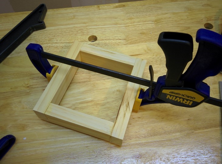
I wanted to make something about the size of the SparkFun box, and it turned out I had some scrap pieces of pine that could be made into a box-like shape with enough room inside for the electronics. A slot for the FTDI breakout board was cut out in�the back piece using a few drill holes and cleaned up with a chisel. After that, an application of wood glue and clamping gave me the 4-sided object I wanted.
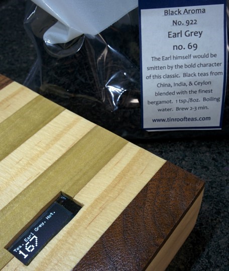
The top of this enclosure would be the most visible part, so I wanted to do something a bit more creative than a plain wood top. I had some scrap walnut and poplar, and with some more of the pine, I cut a few 1⁄8”-thick strips. Luckily, I ended up with enough for a nice symmetrical arrangement. After trimming the pieces to about the correct length, more wood glue and clamping were applied. Once dried, the window for the OLED display was carefully cut out with a drill and fretsaw, and the strips on top were cut (mostly) flush.
Of course, I am no woodworking savant, and there were some, shall we say, rough edges at this point. Sand paper to the rescue! I started with a low grit (~80) to smooth out the edges of the top where they had been cut (mostly) flush, and was able to clean up some parts of the sides as well. Moving on to 150, then ending with 220 grit gave me a pretty nice result.�To give the wood some protection and to really make the colors “pop,” I hit the case with a few coats of spray lacquer. And to be honest, the result is fantastic.
After securing the electronics in place (and verifying everything still worked), the RFItea now occupies a permanent spot on my counter. I’m really happy with how this project turned out. And in working with the RFID reader, I got to learn something new which I can use in future projects. Again, code is available on GitHub, and please let me know if you have any questions. But now, I desire a good cup of tea. I will Make It So.
-Dan


