Weekend Project: NExuS
- microUSB to microUSB Extension Cable
- IEC320 C7 Socket
- Ethernet Coupler
- 8” HDMI Extension
- Right Angle microUSB Cable
- microUSB Ethernet Adapter and USB Hub
- NES Gamepad Hookup PCB (more on this below)
- M4-0.7 screws (10-16mm length)
- Printed brackets (more on this below)
- 16 AWG Wire
- Female 2-prong socket end
- Hot Glue
- Quick Set Epoxy
- Low Grit Sandpaper
Introduction
I’ve had an NES (my wife’s actual childhood NES, in fact) sitting in my parts drawer, with the intent of ripping it apart, gutting it, and jamming in a Raspberry Pi to make an awesome emulation box since… well, ever since the Raspberry Pi came out. Then the Raspberry Pi 2 was released and I got one to use that instead. It can play PSOne games, after all. But other projects got in the way and I just hadn’t gotten around to it. But a few weeks ago, I was on Amazon.com for something else, and they suggested the Nexus Player which I already have and love. I’d been wanting to pick one up anyways to replace the combination of an old Roku and a Raspberry Pi running Raspbmc on our living room TV.
Luck had it that the Nexus Player was on sale and I suddenly had a thought… It runs Android. It could do much more than just retro games. And, surely there are supported game console emulators… A few minutes of searching confirmed that yes, there were some great ones for NES, SNES, Atari, and a few others. It supported the main three that my wife and I were interested in, so I ordered the Nexus Player and, later that night, started gutting the NES.
The Plan
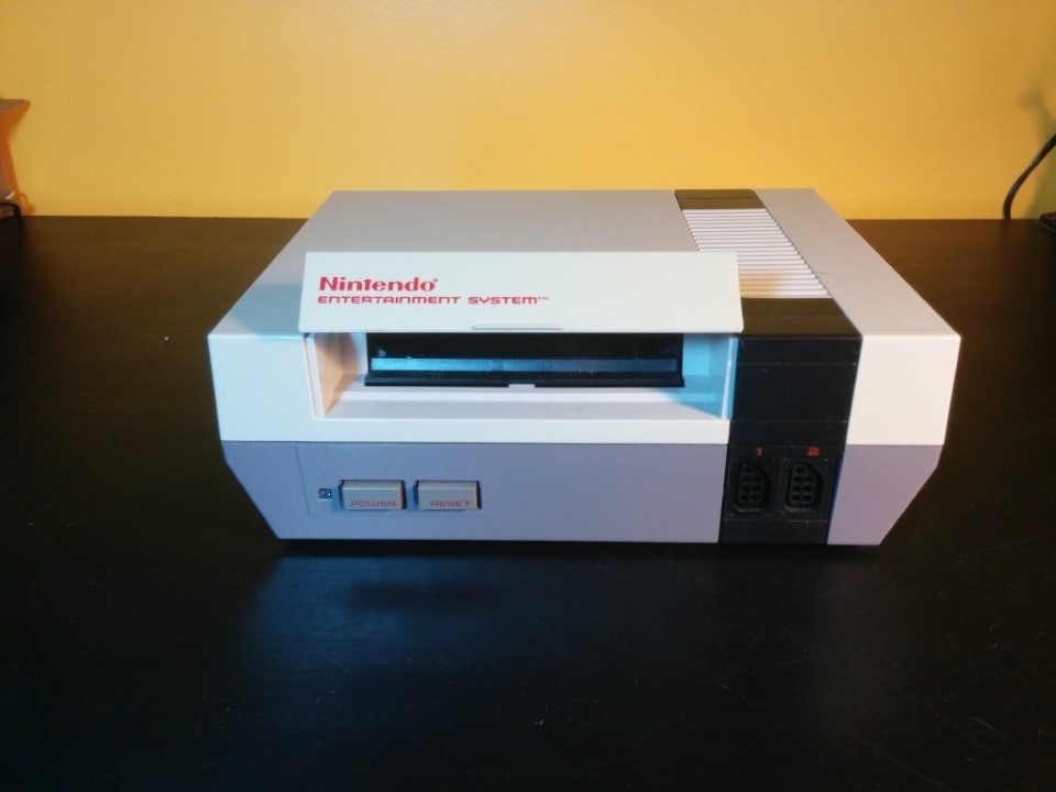
My main desires for this build was that the NES look completely stock and unchanged from the front and that original, unmodified, NES gamepads worked via the original gamepad ports. Fortunately, this turned out not to be too bad. First, I needed all the extra parts that would allow me to break out power, network, and video for the Nexus player, and to hook up some extra peripherals. Some I already had lying around, some I had to order but for all parts, these are the exact items:
Also needed were:
Teardown
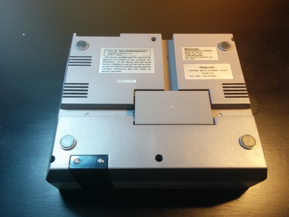
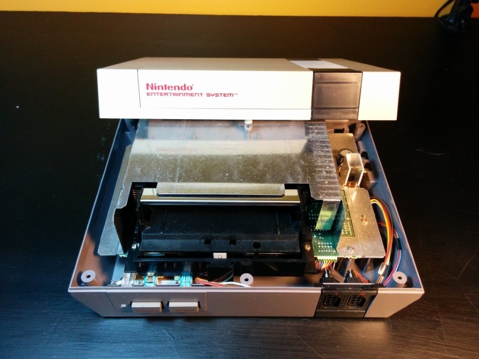
I miss the 80’s. For a lot of reasons, but one of them being that they just don’t make things now like they did back then. The NES, unlike modern consoles, was crazy easy to pull apart. Every screw, except two, in the entire thing was exactly the same, and they were all basic phillips head! Start by removing 6 screws on the bottom, then flip it over and remove the top.
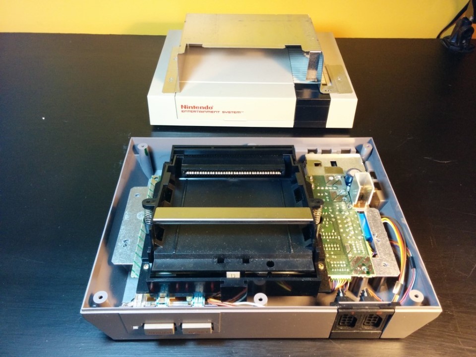
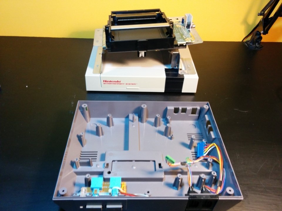
Next, remove all the interior screws you see and pull out the motherboard. You will have to also disconnect the power connector and two gamepad connectors.
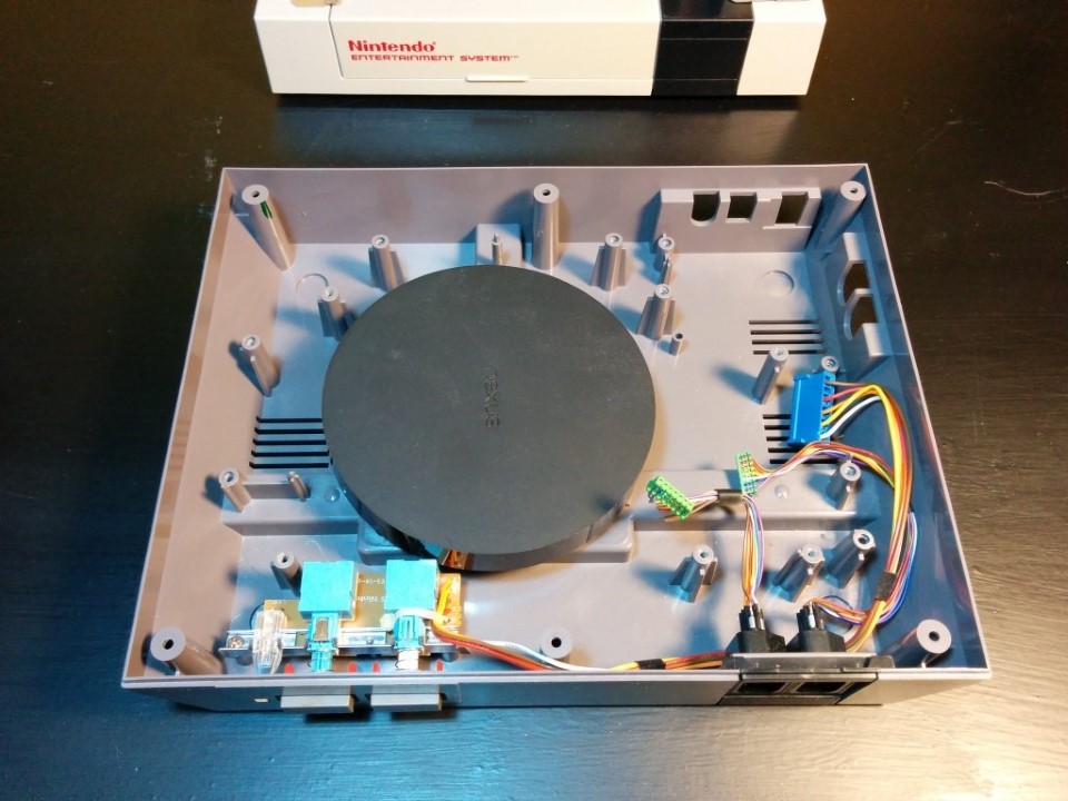
As you can see, the Nexus Player fits quite nicely in between all the original screw posts, though a bit of cutting will still be in order.
GamePads
The gamepads were the major detail I wanted to get absolutely right on this build. Plug in an original NES gamepad and it works. Period. Fortunately, this wasn’t too bad of a task. One of my favorite Arduino boards the Arduino Pro Micro from SparkFun and an NES gamepad library got things started nicely.
I prefer to have easy to hookup, custom PCBs for projects like this but in this case I just wanted to get things working and I had a close-enough alternative. The gamepad sockets do have 7-pin molex-type connectors on them, but they were sadly a weird ~1.5mm pin pitch instead of the usual 2.5mm (0.1”) so I’d have to find the right connector and footprint. Maybe someday, but I already had a breakout PCB for another gamepad project (more on that in a future post) which would work close enough by ditching the connectors and soldering the wires directly to the board. This PCB simply breaks out the right pins from for the gamepads and provides a socket to place the Arduino Pro Micro in. We do this a lot and find it an easy method to get a semi custom arduino without having to actually build all the arduino parts into our PCB.
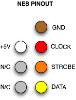
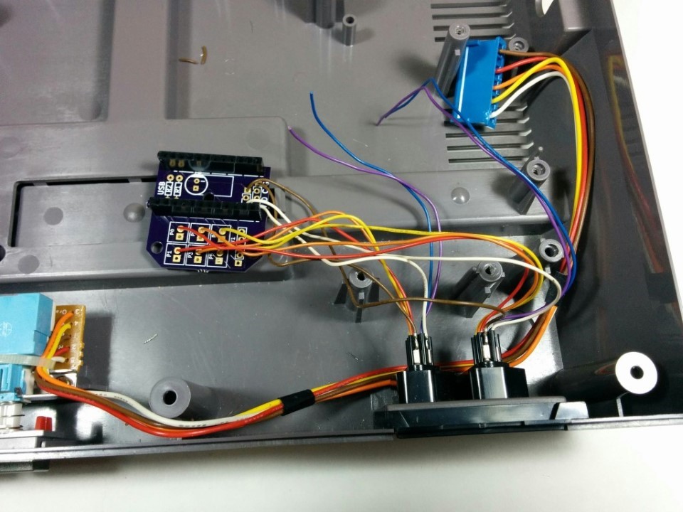
Check the gamepad pinout. The NC pins are the purple and blue wires seen in the picture below. We’ll use P0-P5 on the custom board, in which the square pads are ground (which we won’t use) and the round are input (which we will) and the even numbered pins for gamepad 1 and the odd numbered pins for gamepad 2. Hookup red (clock) to P0, orange (strobe) to P2, and yellow (data) to P4. Then for gamepad 2, use P1, P3, and P5 in the same order. There’s a set of 3 pin and a 4 pin connector beneath where the Pro Micro goes. Hookup brown (ground) and white (5V) as you see in the picture below.
You can find the KiCAD files for the PCB on GitHub or, if you would rather, order one directly from OSHPark. It was actually OSHPark’s minimum of 3 rule that made this even possible… I had 2 left over :)
Now, to make this actually do something. The reason I use an Arduino Pro Micro is that it is based on the awesome ATMega32u4 (just like the AllPixel) which includes on-chip USB functionality. This makes it really easy to make the board show up as a USB keyboard and send keystrokes to a computer. 100 lines of code was all it took to convert the gamepad button presses (for both gamepads simultaneously!) into keystrokes that could be used on anything that supports USB keyboards (yes, the Nexus Player does… more on that in a minute). Download the firmware here to check it out and load it yourself. Note that, since there are two separate gamepads, the firmware uses pretty normal keys for gamepad 1 (arrows, A, B, Enter, Space) and others for gamepad 2. This is no big deal as the above mentioned emulators allow you to map the keys however you want.
Stuffing
So, now I know the gamepads work. Time to put it all back together. I wanted to make sure I didn’t damage the Nexus Player but a lot of this could probably be done with hot glue and creative zip ties, but when you’ve got a 3D printer…
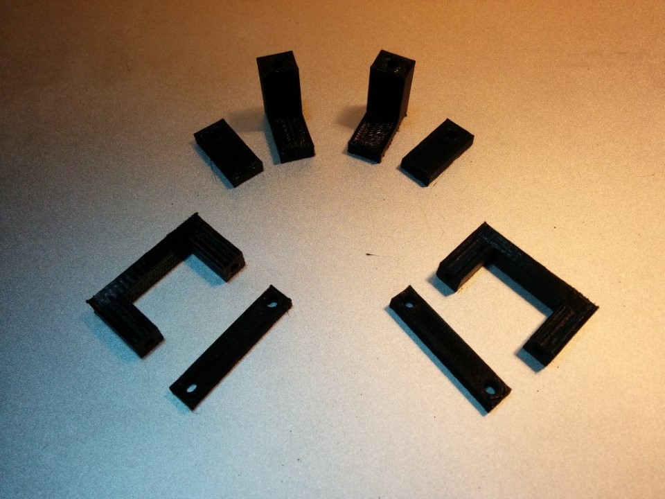
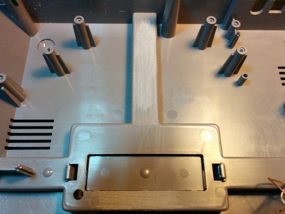
3D printed brackets to the rescue! The above are for the Nexus Player itself (top) and the ethernet/USB adapter (bottom) and are available on the NExuS GitHub repo. But first we have to make a little extra room for the Nexus Player. Use some angled snips to cut off the screw post on the ridge that runs from the expansion port hole (the NES sadly never used this) to the back of the case. Also snip off the little domed plastic nub next to it. Then take some 60 grit sand paper, sand down anything that’s left of what you cut off and then rough up that area and on the other side of the expansion port hole.
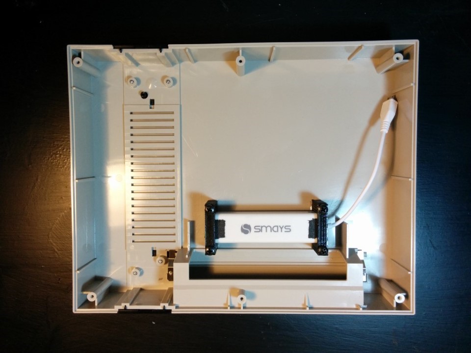
I also decided to place the Ethernet Adapter / USB Hub right inside the cartridge slot. Line up the placement with the brackets on the top of the case and rough up the area below those brackets as well. I recommend marking off their location with a permanent marker to maintain their placement. Do this for the Nexus Player brackets as well, after testing their placement to be sure it fits. They should fit snug up against the curved side of the NP, which will be held in place once the top part of the bracket is screwed down.
Prepare some quick set epoxy and carefully place the brackets as shown in the picture below. As long as the case is on a flat surface and the plastic was properly roughed up, there should be no need to clamp anything in place. Just leave it sit for a good hour to fully set.
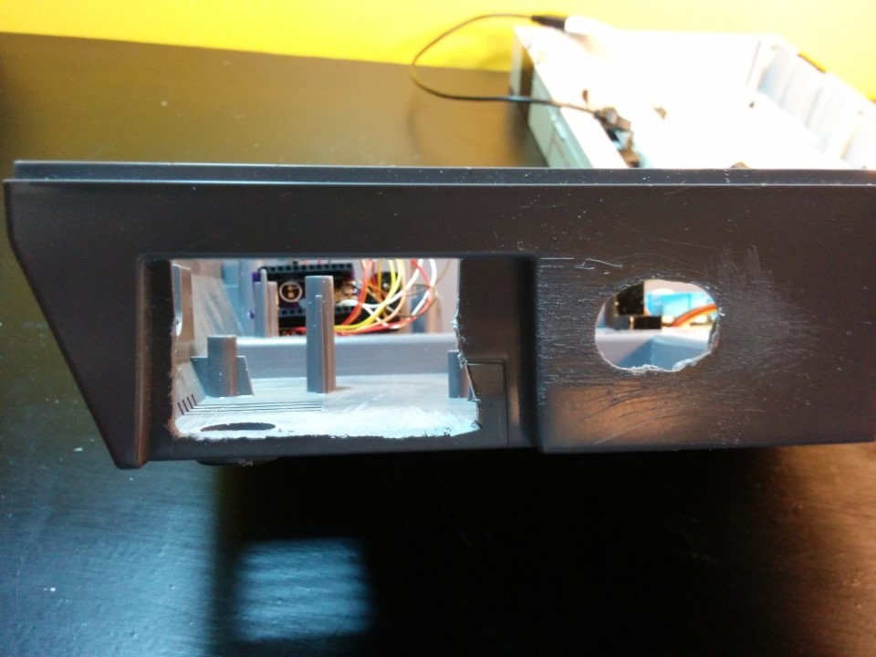
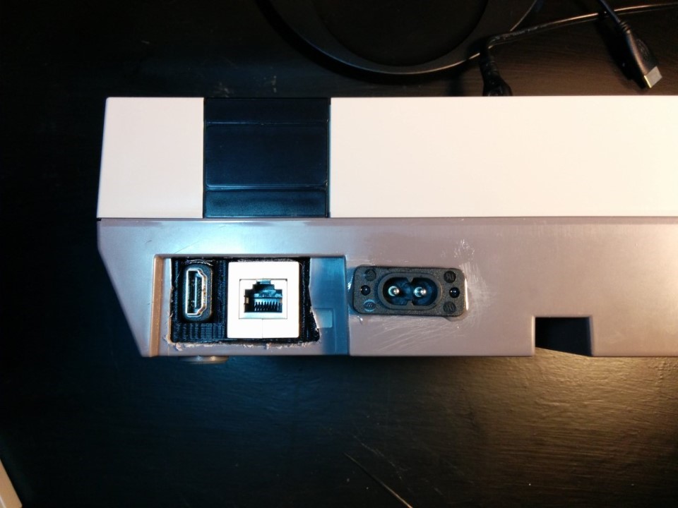
Next, cut a hole where the back power and video ports were with a small-toothed saw or a file. Then, to the right of that, drill out a slot large enough for the IEC320 power socket to fit. I used a 1⁄2” drill bit to start and then carefully pushed the spinning bit sideways to chew out the rest of the slot. Not pretty, but it worked.
Rough up the bottom of the case near the opening you just cut for the inputs and epoxy in the HDMI and Ethernet bracket (InputBracket.123dx from the repository linked above) like you did with the other brackets.
Before installing the power socket, take the the 16AWG wire and solder a 10” length to each of the IEC socket pins. Then cover them with heat shrink tubing. Once this is some, you can epoxy that into the drilled slot on the back. This will take some sort of clamp since it’s at an odd angle and there’s not much to adhere to anyways.
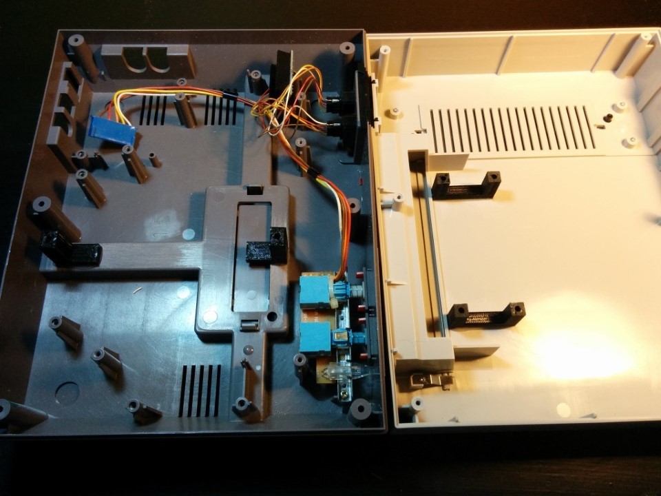
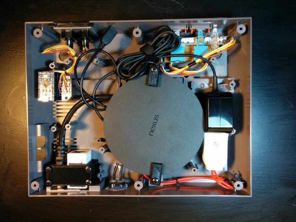
Once that has all set, install the 2-prong female socket to the other end of those wires. This is how the NP power brick will be connected. Then install everything like you see below:
Screw the tops of the brackets in with M4-0.7 screws. I used 16mm long screws but 10mm would work. I used hot glue to hold the NP power brick in place so that it could be easily removed if need be in the future. I also recommend fully covering the power socket back with hot glue, for safety. The gamepad PCB was screwed through its center hole to one of the existing screw posts. Note that all the NP cables should be connected before securing it with the brackets. The microUSB extension cable should be plugged into the microUSB port on the NP between the HDMI and power ports. Contrary to the NP documentation, this is not just for debugging purposes.
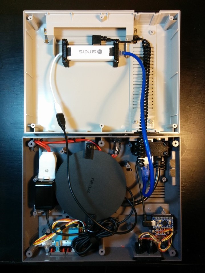
On the top of the case, install the Ethernet / USB adapter with the bracket tops and M4 screws like before.
Now, use the microUSB extension cable that’s already plugged into the NP to connect the adapter. Use a ~12” length of Ethernet cable to connect from the end of the adapter to the Ethernet coupler at the back. Then use the right angle microUSB cable to connect one of the three adapter ports to the Arduino Pro Micro board.
That’s it. Close it back up, screw the case back together and you should be ready to go :)
Software
All the emulators linked above are made by the same developer and use the same (open source) interface, so I’ll just go over setting up NES.emu. Either install it via the given link or go to the Play Store on the NP and do a search for Nintendo. NES.emu should come right up.
Once installed, launch the app, then scroll down to “Key/Gamepd Input Setup”. Under the “Individual Device Settings” section, you should see an entry for “Sparkfun Pro Micro”, select that. Then choose “Set Gamepad Keys” and go through each option and press the corresponding button on the NES gamepad to map it. If you want to map both gamepads, select the “Player” option first and choose “Multiple”. You will then get options for Gamepad 1 and Gamepad 2, map both using their corresponding physical gamepad.
Note that the official Nexus Player (Asus) BlueTooth gamepad will work, as will just about any BlueTooth or USB gamepad, including the XBox 360 controller. You can even find a ton of NES/SNES/Sega/etc. clone but USB gamepads online for a handful of dollars. They all can be keymapped in the same method. We use the original NES gamepads for NES and Atari games, but the NP BlueTooth gamepad and an XBox controller for SNES games. There’s also a Coleco Emulator but the Coleco controller is unlike almost anything else… so I’ll be building a USB converter for that as well in the near future.
Finally, you will also need to load the game ROMs onto the local device storage (there’s ~8GB but most ROMs require less than 100KB each). Install ES File Explorer on the NP and then use it to either copy the games from a USB stick (using the USB hub inside the cartridge slot) or via a network share. Then, in the main menu of NES.emu, just choose “Load Game” and browse the the desired ROM.
That’s it! Happy Gaming!

