IR Remote Controlled TV Bias Light
- Arduino Pro Mini
- TSOP38238 IR Sensor
- WS2801 LED strip
- Misc. connectors
Now that the AllPixel boards are finally landing in the hands of our backers, I felt it was time to take on one of the projects on my very long and neglected to-do list. Something to clear my head a bit… but let’s be honest, it’s still going to be LED related :)
I’ve wanted a bias light for a long time and recently got the idea that it would be cool to make it controllable with an IR remote. I wanted to learn how to interface with an IR receiver on the Arduino anyways, so it was a good excuse. In total, this build was quite simple in terms of parts. All I used was:
Now, I know, some are going to ask me why I didn’t use the AllPixel… well, while I stand by it as an awesome tool, it would have been serious overkill and quite a lot more complex. The AllPixel requires another computer to control it, which would maybe have made more sense if I wanted to control it directly from a media PC or something, but I wanted it to be more standalone. If I ever want to upgrade this to an Ambilight clone, then the AllPixel would definitely be the way to go.
Speaking of overkill; I should note that using the WS2801 strips was definitely more complexity and expense than was needed. The best solution, since I wanted the strip to all be the same color, would be an “analog” LED strip without individual pixel control. This would have been much cheaper. Or even a 12V WS2801 strip where each “pixel” is 3 LEDs, which are also a good deal cheaper. But there’s cheaper and then there’s what I already have in my parts stock. Going with what I had on hand made it a nice and quick project. Just keep in mind, if replicating this, there are cheaper options if you don’t already have the parts.
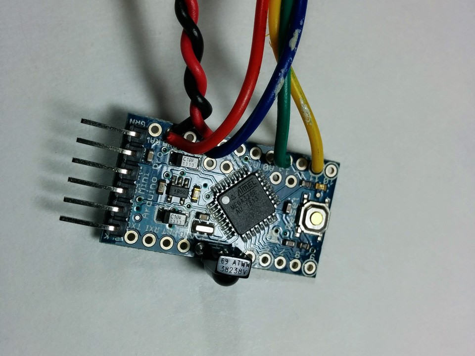
The hookup is pretty simple. First, follow the TSOP38238 datasheep and connect pin 1 of the sensor to pin 2 on the Pro Mini, 2 to 3, and 3 to 4.
What I did with the pin hookup here is cheating a little. I didn’t want to require any fancy wiring, so I just use Arduino pin 2 as the input pin, but then set pin 3 as OUTPUT/LOW (Ground) and pin 4 as OUTPUT/HIGH (VCC). A nice little trick when you have extra pins and want to power something lower powered without having to connect to proper Ground and VCC. You just have to add the following code as the first thing in setup():
    pinMode(3, OUTPUT);
    pinMode(4, OUTPUT);
    digitalWrite(3, LOW);
    digitalWrite(4, HIGH);
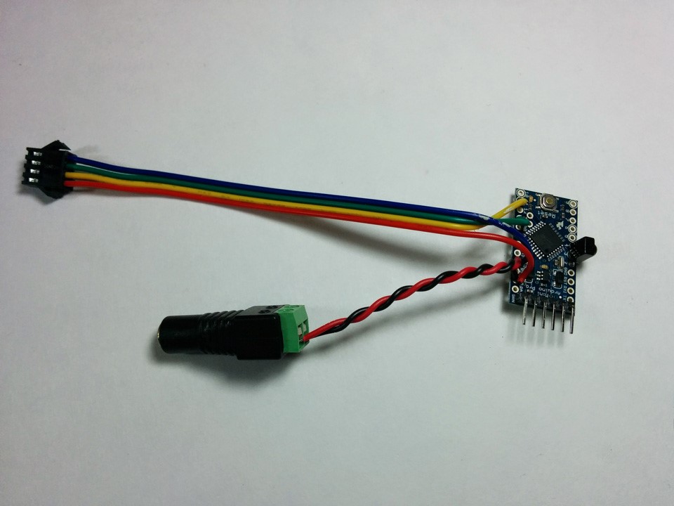
Next, hook up the LED strip connection. I used a 4 pin JST connector (since that’s what is on the LED strip) and wired the Data line to pin 11 (MOSI) and Clock line to pin 13 (CLK). Then, VCC and Ground were connected to the VCC and Ground Arduino pins, as were two more wires that I connected to one of the handy screw terminal barrel jack adapters I keep on hand. Connecting the power this way allows powering both the LED strip and the Arduino off the same 5V power adapter.
For the software, I used a great IR library called IRLib which really makes reading the IR input super easy. The LEDs were, of course, controlled by the awesome FastLED which is also at the heart of the AllPixel :) You can checkout all the final code at the IRBiasLight GitHub repo but I want to make a couple notes:
- Change the following line to reflect the total number of LEDs your strip has.
#define numLEDs 103
- Every remote is different and uses different IR codes. So you will have to program the codes of the remote you want to use. The code outputs the code of every remote signal that it receives to the serial console. Just set the console to 115200 baud and then press the buttons you would like to use for each function and past those values into these lines:
#define BRIGHT_UP  0xE0E006F9      //Remote D-Up
#define BRIGHT_DOWN    0xE0E08679  //Remote D-Down
#define COLOR_BK   0xE0E0A659  //Remote D-Left
#define COLOR_FWD  0xE0E046B9  //Remote D-Right
#define HOME       0xE0E0B44B  //Remote Exit
#define SAVE       0xE0E058A7  //Remote Menu
#define POWER      0xE0E016E9  //Remote Enter/OK
#define RAINBOW        0xE0E024DB  //Remote Sleep
I used a remote from an unused device so that the remote codes would not conflict with anything. Even though I will program these codes into my Logitech universal remote, it’s unfortunate that the only way to do this is from another remote and not by directly entering a remote code. So, I cannot just enter any arbitrary code that I want. But it probably won’t be too hard for you to find an old remote lying around. Though, note that some may not work as it has to be a remote that uses a 38kH carrier signal supported by the TSOP38238. Most modern remotes use this frequency, but not all. So if nothing is output over the serial connection, just try a different remote.
The functions listed above perform the following actions:
- BRIGHT_UP: Increase brightness
- BRIGHT_DOWN: Decrease brightness
- COLOR_BK: Increase color hue, cycles through full spectrum and then white
- COLOR_FWD: Decrease color hue, cycles through full spectrum and then white
- HOME: Revert to saved color and brightness
- SAVE: Save current color and brightness for recall by HOME function
- POWER: Turn the light off. Every other action turns them on
- RAINBOW: Displays a rainbow gradient… because we can :)
All above functions except, of course, power will turn the LEDs on if they are currently off.
Post in the comments with any questions. Happy making!


