The ESP8266: Taking the New Hotness for a Spin
You’ve probably heard about this little module by now; a cheap, wifi-enabled bit of wizardry that is all the rage. Using serial communication, you can talk to the device and send commands out to the interwebs. I’m certainly not claiming to be bringing anything new to the table with this post, but I did want to share some of my experiences, and in particular, some of the hang-ups I ran into.
I set out with a goal: to read temperature data and send it to a data service (data.sparkfun.com, in this case). I did some looking around on the Google and came across a few Instructables that looked like they might point me in the right direction. But no single one would get me from having the module show up at my door to spewing useless temperature data all over the web. There were “prerequisites.”
I’m all about the efficient communication of information, so here’s a list of key “Lessons Learned,” a sort of ‘TL;DR’
Key Lessons Learned: 1) Since they are 3.3V devices, a [logic level converter](https://www.adafruit.com/products/757) is needed to communicate with them if you're using a 5V FTDI module/cable. I knew this going in, but it's worth mentioning if it avoids frying electronics. 2) They may not default to the expected baud rate when you get them. Try 9600 and 115200 first, and then other speeds in between if needed. 3) The tool I used to flash the firmware was expecting 115200 baud and wasn't clear about it. 4) GPIO0 must be grounded to put the device into "firmware flashing mode." 5) The arduino SoftwareSerial implementation is limited in speed when using an 8MHz CPU setting. Setting the module and the SoftwareSerial speed to 9600 baud worked fine. 6) During the data transmission part of the code, a post-transmit delay of a few seconds was added. I found this was needed to ensure the ESP8266 sent the data correctly before it was powered down.
Step 1: AT OK
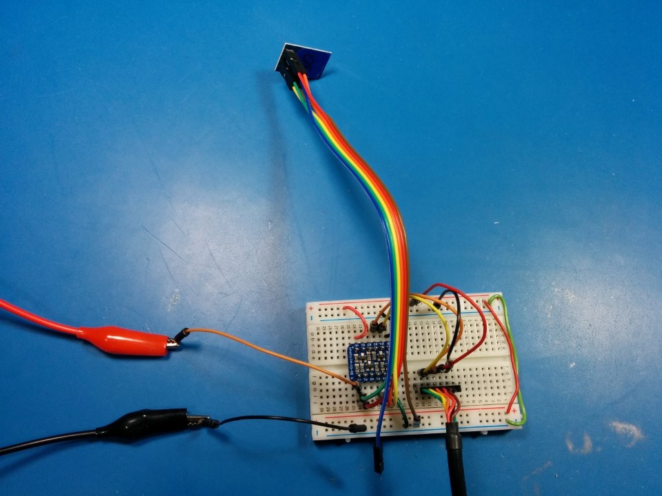
Once I felt that I had enough basic knowledge to warrant spending actual money, I placed an order, and a short time later, took delivery of two ESP8266 modules. I knew that they could be reasoned with, provided I spoke their language. In this case, 9600 baud. Also, since I would be using my USB FTDI cable, and since these and others like it are 3.3V devices, a level converter was needed.
For the initial wiring, I referenced this site, specifically the pinout and the Firmware section:
For my setup:
UTXD -> Level Shifter -> FTDI TX URXD -> Level Shifter -> FTDI RX VCC -> 3.3V CH_PD -> 3.3V GND -> GND GPIO0 -> grounded for flashing firmware, not grounded for normal operation (see the ‘Module Pin Description’ section on the ElectroDragon site linked above)
With the connections made and power applied (and no Blue Smoke events), I attempted to connect. Some places say these devices default to 115200 baud, which depending on the firmware, they might. Mine, however, had older firmware and defaulted to 9600. Once that was figured out, I was able to talk to the device. They use AT commands, so sending ‘AT’ would elicit an ‘OK’ response. I was in.
Step 2: Obtain Firmware, Apply Liberally
So now that I was able to talk to the device, it was time to update the firmware. Of course, easier said than done. I’ll spare you my tales of woe and just describe how I eventually got it to work.
At the very bottom of the ElectroDragon site linked above, there’s a ‘Documents’ section with a link to the Google Drive folder containing the firmware images and the tools needed to flash said firmware. From that top level folder ‘ESP8266’, I went to ‘Firmware’, ‘AT_Bin files’, ‘New-AI-v0.9.5.0 AT Firmware’ and downloaded the ‘AI-v0.9.5.0 AT Firmware.bin’ file. Going back to the top level, from ‘ESP8266’, I went to ‘Tool’ and downloaded the ‘esp8266_flasher_simple.zip’ tool. This is a simple executable where all you do is provide the COM port you’re using and the path to the bin file and the program does the rest, assuming you are able to communicate with the module.
Note: For this tool, I found, after much wailing and gnashing of teeth, that it requires the module to be set to 115200 baud. Again, I’ll spare you the Woe Tales. But this is how you read and change the baud rate on these devices:
**AT+CIOBAUD?** : return the current baud rate (which you should already know since you’re talking to it in order to send the command…) **AT+CIOBAUD=115200** : will set the baud rate to, in this case, 115200
As mentioned above in the connection list, GPIO0 must be grounded in order to flash new firmware. Once the “correct” baud rate was set and GPIO0 grounded, the firmware did flash, and Lo, it was Good.
Step 3: Get Ye Wifi
Now, with the firmware updated, it was time to try and get the thing to connect to my wireless network. I found this page of an Instructable to be very helpful. I more or less followed those instructions exactly. But here it is written out anyway:
**AT+RST** : Reset the device **AT+CWMODE=3** : “set the module as both a client and an access point” **AT+CWLAP** : Lists networks in range **AT+CWJAP=”SSID”,”password”** : connects to provided network using provided password **AT+CIFSR **: shows device IP address information
It works! Hooray! And that’s pretty much it for the wifi connection part. The device will now reconnect to the provided network on powerup. At this point, I was able to talk to the device over a serial connection, and the device could talk to my wireless network. The next step would be to send some data through that serial connection, through the wireless, and out to the Internet.
Step 4: Actually Doing Something
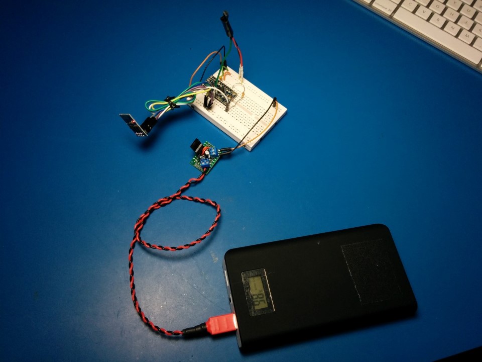
Here’s where it gets interesting. One of the reasons I was attracted to the ESP8266 was its low cost. ~$8 US for wifi connectivity is quite attractive. Pair that with a ~$5 Arduino Pro Mini knock-off from eBay and you’ve got the makings of a cheap yet powerful data collection and transmission platform. I happened to have a few said knock-offs. You know, just to see if they were any good. For the purposes of these tests, they will work fine. If you’re going to be making something for a permanent installation or if you’re making something for someone, I’d recommend using the official ones. Since they are of the 3.3V 8MHz variety, no level shifting was needed and both APM and ESP8266 could be powered off the same 3.3V supply.
For this part, I referenced this Instructable a bit, but made a number of modifications, mostly in the code. The end result is that every set period of time, the device reads the temperature sensor and sends the value to a data.sparkfun.com stream by formatting a string to send over the SoftwareSerial connection to the ESP8266.
I have used the DS18B20 digital temperature sensor for a number of other projects, and I really like them. They use the one wire protocol, are individually addressed, and are acceptably accurate. Again, without going into the gory details of finding the right wiring configuration for the sensor and the ESP8266, here it is in list form for easy consumption:
ESP8266 UTXD -> APM Pin 3 ESP8266 URXD -> APM Pin 2 ESP8266 VCC -> 3.3V ESP8266 GND -> GND ESP8266 CH_PD -> 3.3V ESP8266 RST -> 10K Resistor -> APM Pin 13 DS18B20 VCC -> 3.3V DS18B20 GND -> GND DS18B20 DATA -> APM Pin 4
I had some trouble initially getting the code to talk to the ESP8266. The code uses SoftwareSerial to talk to the ESP8266, and the hardware serial bus for debug purposes. Again after much wailing and gnashing of teeth and mental table flipping, I discovered that the 115200 baud setting on the module was the problem. I knocked it down to 9600 and the code was able to talk to the module over the SoftwareSerial port no problem. My esteemed colleague pointed me towards this and this. As I had discovered, there are limits on how fast SoftwareSerial can transmit and receive. Fortunately, for my purposes, 9600 baud is well within those limits and should do OK for what I need (although I could speed it up a little bit to maybe 14400). So Hooray for learning something.
Once I could confirm that the code could talk to the device, I made a few changes to get rid of the built-in wifi connection establishment. Since I had configured the ESP8266 to automatically connect to my network when powered on, it wasn’t necessary for the microcontroller code to try and do this. I did keep in the module check, which sends a simple ‘AT’ and makes sure ‘OK’ is received in reply, indicating that the module is present and communicating.
I also changed around how the code turns on and off the ESP8266, in the interest of conserving power. In short, the Reset pin on the ESP8266 is connected to pin 13 on the APM through a resistor (I don’t think the resistor is strictly needed, but I did it just to be safe). Prior to each “transmission”, the pin 13 is sent high, which enables the module since it is an Active Low reset. After a short delay to acquire a network connection, the temperature data is sent. After another short delay to make sure the data is sent successfully, pin 13 is sent low, which grounds the ESP8266 reset pin, thus holding it in reset.
I think there are better ways to handle putting the ESP8266 to “sleep” to save more power, and I can certainly play with sleep settings on the Arduino Pro Mini to save even more power. Since the whole setup requires 3.3V, a lithium ion battery should work to power the device for quite a while, assuming proper power regulation techniques are used. For now, though, the current proof-of-concept is sufficient. I have a cheap wireless temperature sensor that reports data to an online data aggregator. I claim Victory.
I’ve posted the code I used to our github for your viewing and downloading pleasure:
https://github.com/ManiacalLabs/ESP8266TempLogger
Step 5: Next Steps
One of the ways I approach this hobby is to learn how new things work at a basic level, and then draw upon that knowledge in the future for other projects. With this experiment, I now have a new tool in my proverbial Bag of Tricks. I don’t have any projects currently where I would use the ESP8266, but now that it is a viable option, I’m sure opportunities will present themselves.
I hope that this write-up has been helpful. If you have any questions, or if you’ve found that I’ve left out a critical step or explanation, please let me know.
Also, be sure to check out our YouTube channel for continued content of varied educational and entertainment value.
-Dan


