Raspberry Pi QuadTempProbe: Temperature Measurement and Logging
A friend asked me a few days ago if I knew of a way to remotely monitor multiple different points of temperature, log the data, and generate an email alert if sensor reading went out of bounds. Since I happened to have a ‘project-in-progress’ with just that goal, I decided I should finish it. Or, rather, get it to a working state.
Hardware:
  * Raspberry Pi (model B used, will work on B+)
  * [WiFi adapter](http://www.adafruit.com/products/814)
  * Powered USB hub (optional, depending on how your wifi module behaves)
  * [DS18B20 Temperature Sensor](http://www.adafruit.com/products/374)
  * [ZVNL110A N-Channel MOSFET](http://www.mouser.com/ProductDetail/Diodes-Incorporated/ZVNL110A/?qs=Fd5IDHV0WqxzVFiJ%252bmmDdA==)
  * (2) 10K resistors
  * 4.7K resistor
  * (4) [3-Pin JST connector sets, male/female](http://www.ebay.com/itm/Micro-Mini-JST-Connector-1-5mm-3-pin-w-Wire-x-10-sets-/151334550789?pt=Radio_Control_Parts_Accessories&hash=item233c3dfd05)
  * A bunch of telephone wire (or other 3+ conductor wire)
  * A few bits of protoboard
  * Female headers (2 rows of 13)
  * Electrical tape and heat shrink tubing (large)
Software:
  * [Python Phant Library](https://github.com/matze/python-phant)
  * [DS18B20 RasPi Library](https://github.com/timofurrer/ds18b20)
  * [QuadTemp python script](https://github.com/ManiacalLabs/QuadTempProbe)
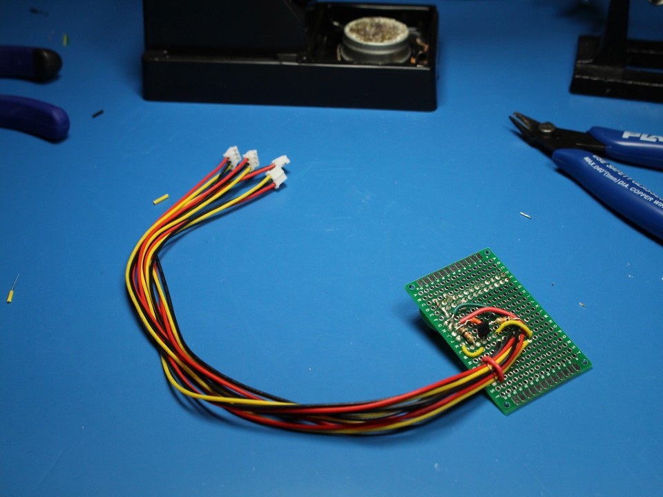
To make installation easier, I built a custom…whatever they call things that attach to the Pi (“plates”?). It uses a ZVNL110A N-Channel MOSFET to do the level conversion for the sensors. They will actually work at 3.3V, but I wanted to use higher voltage due to the length of the wires (~20’), just to be on the safe side. Other than the MOSFET, the board has the 4.7K resistor for the sensors and 4 3-pin JST connections. I’ve included a schematic below that shows how all of this is wired up. Note that the JST connectors aren’t entirely necessary, but they do make installation/re-configuring/removal easier. You could always hard-wire the sensors to the board.
I used the DS18B20 digital temperature sensors for this project, and will probably use them again for similar projects. These things are awesome. No messing around with analog conversions, or having to worry about longer probe lines messing up the readings. And there’s a Pi library already built for them. All the sensors need to function is power and one resistor on the data line for all sensors (they can be wired up in parallel). They use some weird digital protocol to send data, but since it’s digital, there’s no big worries about line noise (there are limits, obviously). Each has it’s own unique ID hard-coded, so you can tell which sensor is reading which temperature.
To extend the reach of the sensors, I used about 20’ of telephone wire for each. I was able to find a 1000’ spool of the stuff on the cheap a while ago, and it’s perfect for this application. It’s flat and flexible, making it great for use in a refrigerator/chest freezer or closed in a door/window. There are 4 conductors, so for the 3-pin sensors, I just twisted two of the wires together on each end. I found that using small scraps of protoboard made the soldering MUCH easier, and added some additional strength to the connections. Judicious application of electrical tape and heat-shrink tubing should make them fairly weather-resistant, but some other sealing method might be preferred (keeping in mind not to interfere too much with the sensors).
So that’s all well and good, but what to do with the measurements? In short, I have a cron job running every 5 minutes that executes the script to poll each sensor and sends the data to a data.sparkfun.com stream. Also in that script, there are toggles and thresholds for alerts on each sensor. If the alert is enabled, an email will be sent to a defined address whenever the corresponding sensor reading goes above the defined temperature. My friend was looking to monitor a chest freezer that was suspected to be faulty. Having a “too warm” alert would indicate a possible failure of the cooling system and potentially give enough advanced warning to save the food inside.
To configure cron to run the python script:
sudo crontab -e -u root
Add the following line to the end of the file to run the script every 5 minutes */5 * * * * sudo python /home/pi/quadtemp.py
And that’s pretty much it. As with most of my projects, I plan on putting more polish on this one in the future. I’d like to design an actual PCB, as opposed to using protoboard and a bunch of wires. When I get that put together, I’ll post about it. If you have any questions or suggestions, let me know.


