24x24 LED Matrix Build
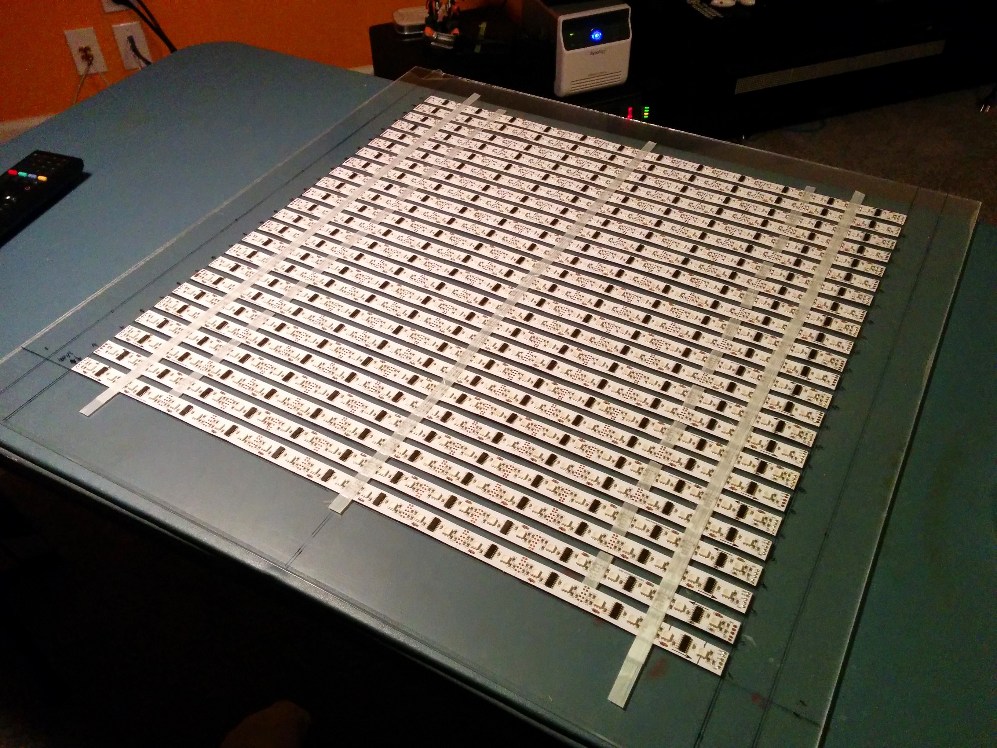
This project was briefly teased before, but it seemed like a good time for more details. Originally conceived as a coffee table build,it quickly morphed into what will eventually become a wall hanging and has been a test-bed for a lot of my LED work. Having worked a great deal with a variety of these digital LED strips, I noticed that in most cases they were manufactured in 0.5m sections and soldered together to form 5m strips. This is usually fine, but also means that the distance between pixels at the solder joint is 2-3mm shorter than the rest of the pixels. Being the type of person that wouldn’t be able to stop twitching over a few pixels in a matrix being misaligned from the rest, this just wouldn’t do. So the best solution was to make each row out of exactly one of these sub-sections so that all pixels are perfectly aligned. Not wanting to un-solder all of the joints to get at the 0.5m sections, I reached out to the manufacturer I typically order from in China about getting the strips in the raw sub-sections. Fortunately, they obliged. Armed with 24 half meter sections of LPD8806 strips, each with 24 pixels, I got to work laying out an evenly spaced grid on a sheet of acrylic.
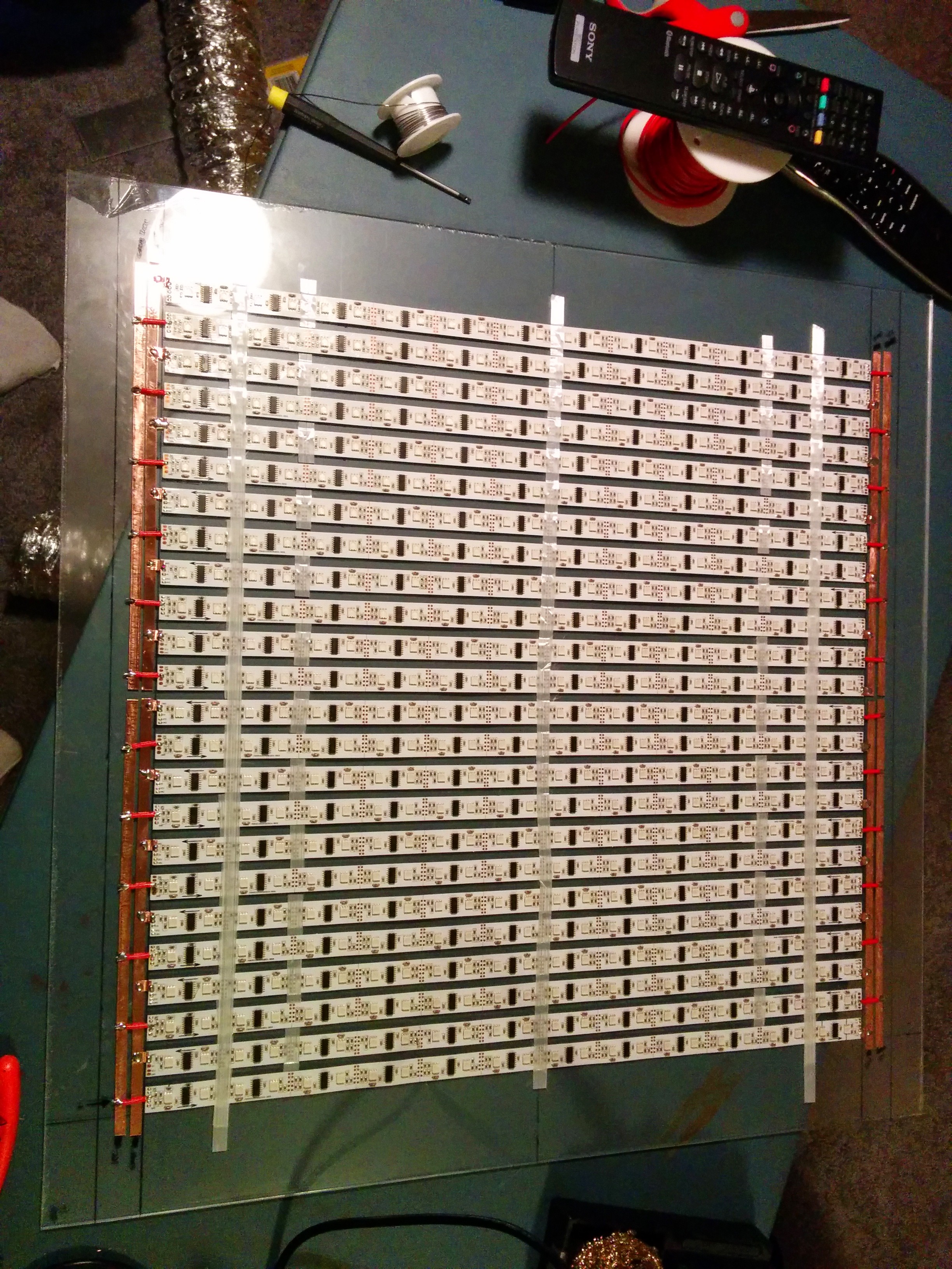
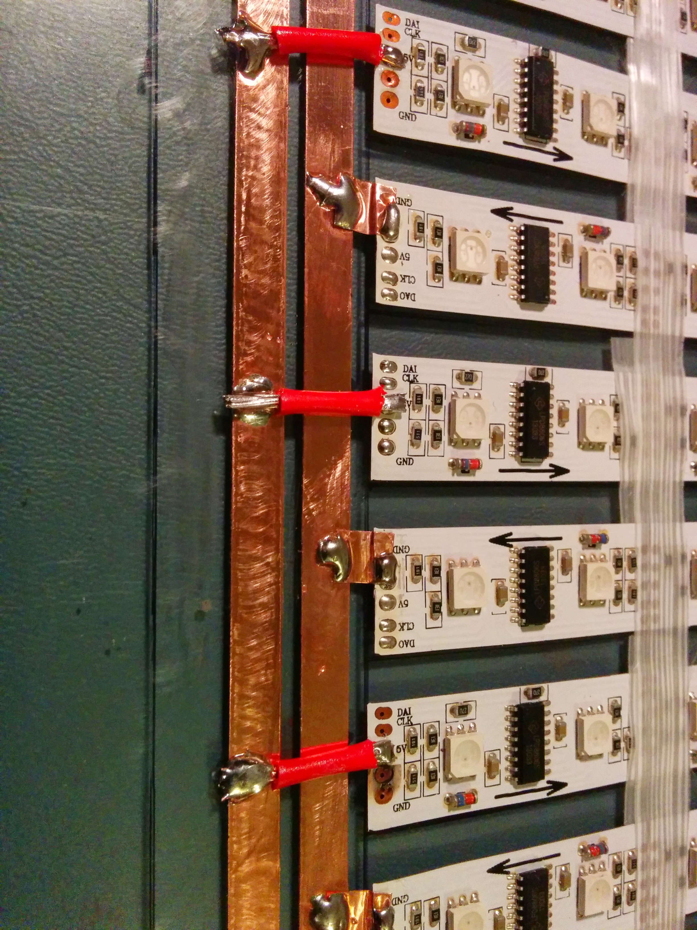
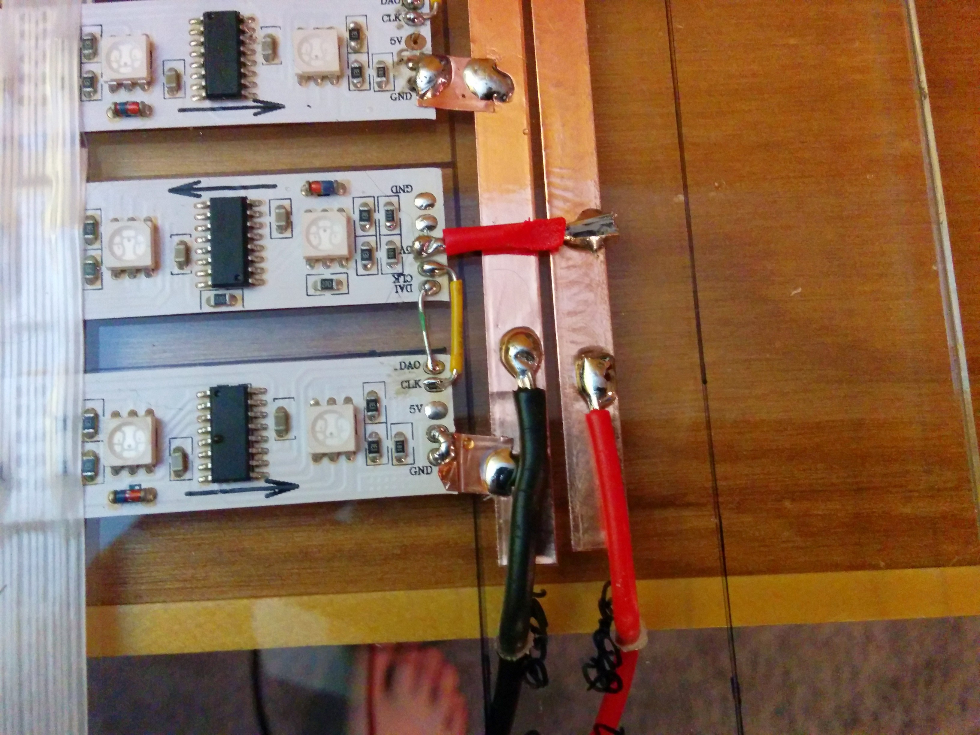
After a couple laborious hours of laying out a perfect grid with a 24” square and a lot of patience, I taped each of the LED strips with a rubber adhesive based strapping tape which I’ve found adheres extremely well to acrylic. Since it had to be wired as one continuous strip, the direction of each was alternated for every row. But first, power buses need to be created to provide the almost 34A (@5V) current the 576 pixels could draw. Originally, I wanted to design a 0.5m long PCB that would handle all of the power and signal routing. But I quickly figured out that I would need two separate designs (the signal pins are farther apart on one side than the other) and that a PCB that long, even a thin one, would cost nearly $75, per design, from OSHPark. $150 for power and signal routing was just too expensive for this project, so I had to find a simpler solution. Using large gauge wire seemed logical at first but stripping all of the insulation in the right place and soldering would be finicky. Copper tape came to the rescue; providing enough of a current capacity, in an extremely low profile. Not enough to carry all of the current on a single bus, but this many LEDs always works best with many small power buses since 5V doesn’t allow for much voltage loss over the length of the power run. The copper tape was laid out in 4 separate buses at the end of each row so that I could use very short jumpers to wire each strip to the bus. Soldering each jumper to took a bit of finesse, since each strip acted as a huge heat sink meaning heat had to be held to the joints for a long time, but not so long as to melt the adhesive or the acrylic beneath. I started by scuffing up the copper with some 100 grit sandpaper and then held my iron to the top of the wire (or the small bit of copper tape I used for the ground bus) and melting the solder into that from the top until it adhered to the bus.
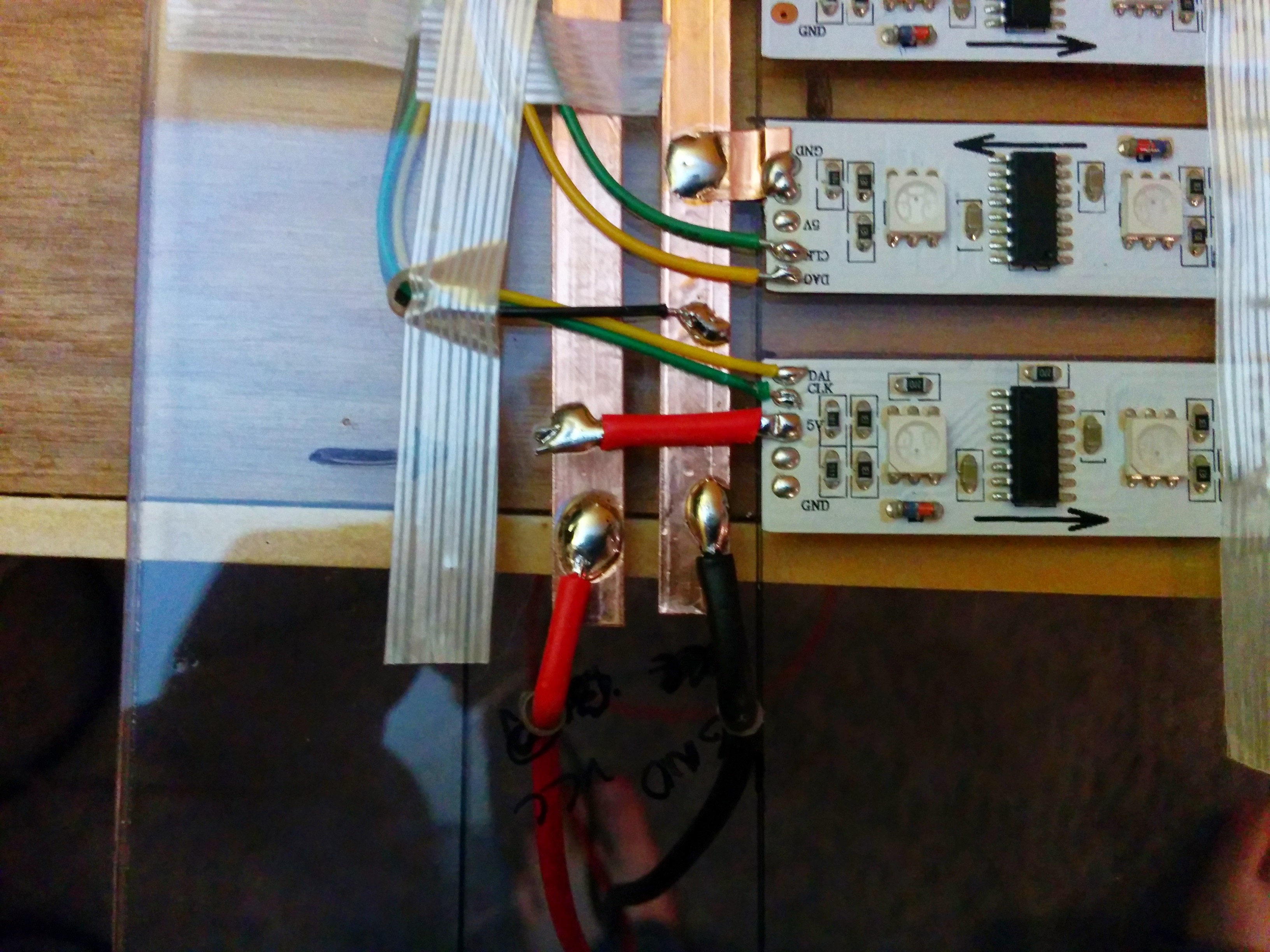
Next up was wiring up all of the data and clock lines. Since the strips alternate directions with each row, one side of the matrix had data and clock pins right next to one another and the other required longer wires that jumped over the power lines. If you start twitching looking at the wire colors on each side… yes, I totally switched data and clock colors between sides. Oops. But with nearly 300 intricate joints to solder in total, it took me three long evenings and a couple movie trilogies to complete. Last was to connect the power bus wires that would connect to a 40A @5V supply and the input signal lines for hookup to the controller. The power lines were connected using some 10 gauge stranded core wire and the signals lines with a long length of phone cable. On the signal wire I also hooked up the ground, for a common signal ground, and 5V line to use for a level converter reference. I always use this converter from Adafruit for prototyping.
On top of all this, at least for now, was placed another sheet of acrylic to make sure nothing touches the power buses or signal lines (especially curious small fingers at the NC Maker Faire!).
that has been modified to handle all of the hard tasks related to controlling matrices made of LED strips. More info on that new library will be coming soon in an exciting update!

