Dial-A-Song: Part 1
- Completely enclosed in an old phone
- Music plays over the headset speaker.
- Raspberry Pi as the brains
- Automatically index all music
- Choose 10 random songs when the phone is picked up and make them available via the menu
- Text to speech for the menu
- Network capable for remote control
Earlier this week, we got the great news that we have been accepted to the North Carolina Maker Faire. We’re absolutely ecstatic to get to share some of our projects with the public but it’s also been a great push to get some other projects done. I’ve had this particular project bouncing around my head for a couple of years now. I call it Dial-A-Song.
Much of the inspiration came from They Might Be Giants, who used to leave recordings of their songs on their answering machine, which could be listened to by calling (718) 387-6962. So, I wanted to combine a little of that with a phone tree menu to give the feel of calling in to a phone service to listen to music of your choice. Yes, it’s a little ridiculous, but why else would I be building it.
As a way of documenting the project and an extra push to keep working on it, I’m going to be writing up a build log in several parts as the build progresses.
So, first, the desired specs:
In part 1, I’ll deal with the phone itself. I really wanted to use an old pay-phone, but good condition models were well over $200, much more than I wanted to spend. So I went for the next best thing:
Who doesn’t want a big red phone on their desk? Only important calls come over a red phone. I found this one on eBay for about $20 and it’s fully functional… now let’s gut it.
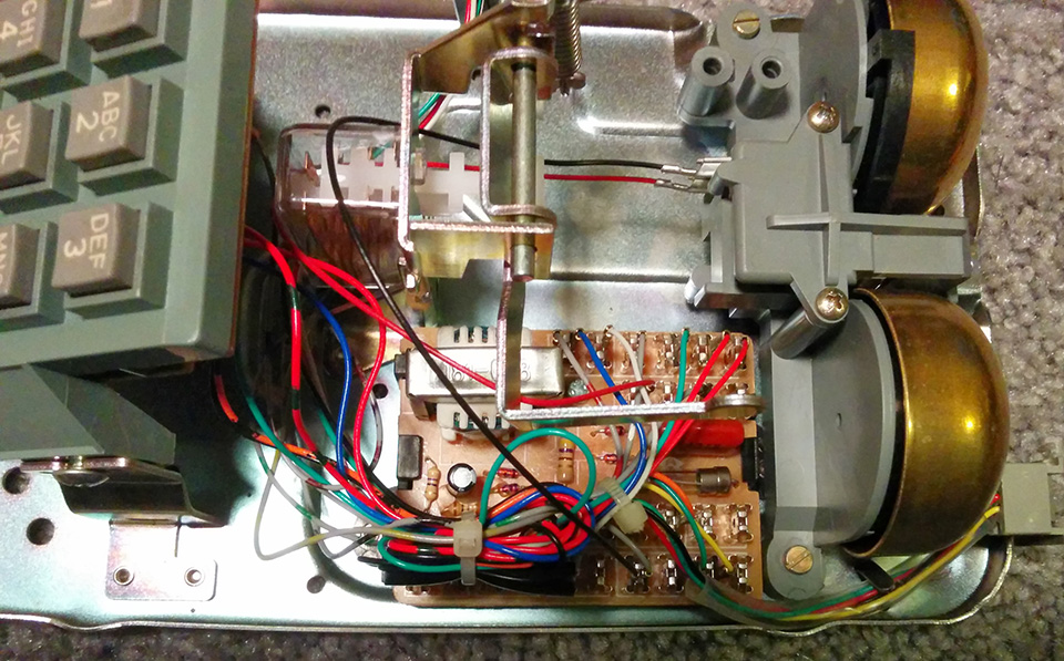
I started by removing the two large, flathead screws on the bottom metal plate. Once out, the entire top casing simply lifts off. As you can see from the interior picture, there’s really not much to these old phones. One PCB on the bottom, another beneath the dial pad, and the ringer assembly, which had to go. I would have loved to keep the ringer intact and actually use it but it takes up too much space and older phones like this run on a higher voltage than I would be working with. They typically run at 48V DC when idle, but a 90V 20Hz AC current is required to actually make the ringer work. So, out it came.
The main board had to go next, as it is really of no use. The only things from the phone I plan on using are the dial pad, the handset and the phone line input (for power and network). I was surprised to see how little was actually on the main board and that it was mostly there just to hook up all the other components of the phone… with removable spade connectors no less. This was definitely a hand-assembled product. The truly don’t make things like this anymore! The only active components on this board are likely for the ringer since it’s the only thing using AC current, making the small transformer and diodes a give-away to their purpose. No matter… to the parts bin it goes.
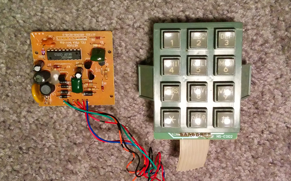
Next to come off is the dial pad assembly. Here’s where the electronics actually get a little interesting. The IC chip on the left is the HM9102C tone generator, responsible for generating the DTMF tones that make a “touch tone” phone system work. The IC reads the dial pad key presses and generates the corresponding tone that gets sent over the phone line. Each row on the dial pad represents a low frequency tone and each column a high frequency. So when a key is pressed, the chip creates a single tone from the two frequencies represented by the row and column of that key, hence the term “dual-tone, multi-frequency” or DTMF. But I don’t need this either - I’m just going to fake the tone sounds in software since they aren’t needed - so off to the parts bin with this board as well.
The dial pad, however, I do need. Fortunately, a little probing with a multimeter shows that it’s wired up like any other matrix keypad ever made. Even better, there’s already a python library for the Raspberry Pi that handles all the heavy lifting of reading the key presses. More on hooking this up in a future post.
Next is the hang-up mechanism. It’s actually much more complex than I was expecting, as it includes 3 separate internal relays. The first (left most) has two switch contacts, one is open when the mechanism is down and the other when it is up. The middle relay opens the circuit when the mechanism is down whereas the right-most relay closes the circuit. Each obviously has a specific purpose, such as connecting the phone line to the handset speaker and mic. But I’m not sure which is which. Fortunately, I only need one of them and don’t really care which direction it goes. I just need to detect a state change via one of the Raspberry Pi GPIO pins and handle it accordingly in the software.
Finally, for this post anyways, is the handset itself. I was a little surprised to see that it had a built in volume control (the wheel in the middle of the handle)… I’ll have to see if there is some way to actually make this work. Unfortunately, I won’t be able to use the volume circuit as is, or the speaker, because they are both designed to run on 48V DC. Whereas I plan to just connect it all to the 1⁄8” audio jack on the Raspberry Pi. The major problem with the speaker is that, as a quick check with my multimeter showed, it has an impedance of over 100 ohms! It makes sense given the voltage it is supposed to run at but that is huge compared to the typical 4-8 ohms of modern speakers. So, instead, I’ll keep the wiring but replace the speaker with one from an old pair of headphones. Likely with both the right and left signals going to the same speaker.
That’s all for now. As this project continues I will post new articles following the progress. Stay tuned!


