Earlier this year we released designs for the Engravinator and while designing that, I caught the CNC bug… hard. I’ve been using all sorts of CNC-type machines for years, of course, already owning multiple 3D printers, lasers, and CNC routers. What I mean is the bug for building my own.
The Engravinator is a great little machine and that’s what it’s designed to be. Small. But I quickly wanted to be able to work with much larger material and have a level of flexibility that the Engravinator just did not afford. So for a few months, the idea of a roughly 1 meter by 1 meter, 2-axis motion system rumenated in my mind.
It needed to not only have a large working area but have but the flexibility to use more than just a laser or pen as a toolhead. It needed to be a development platform for all my computerized motion control needs. And while I wanted it to be accessible in terms of the ability to replicate the design (which of course makes future repairs simpler for myself as well), I wanted the over-arching philosophy to be:

So when things, well… got crazy in March 2020, I decided it was a good time to barricade myself in the shop and start chipping away at a design. And, well, it turned it out to be a pretty awesome machine, if I do say so myself :)
Specs
Let’s get right to the good stuff, shall we?
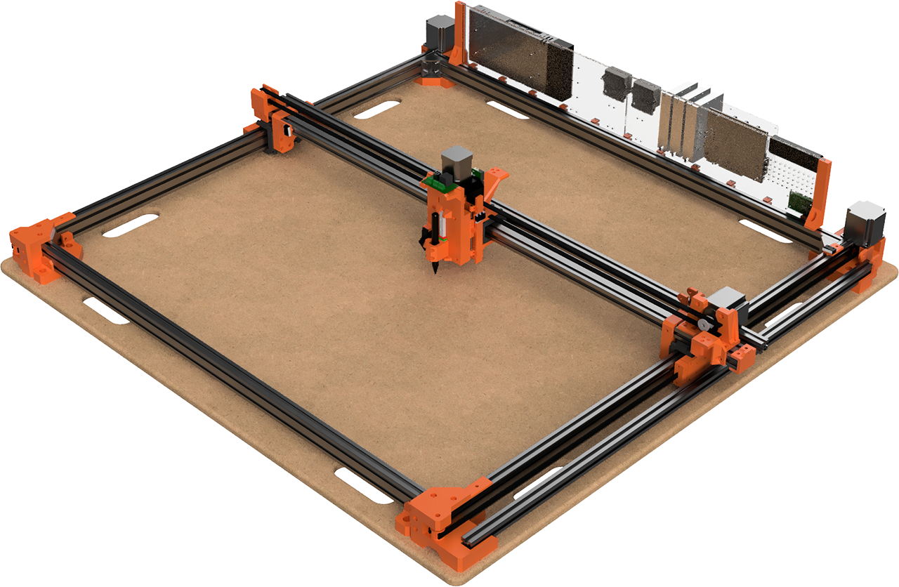
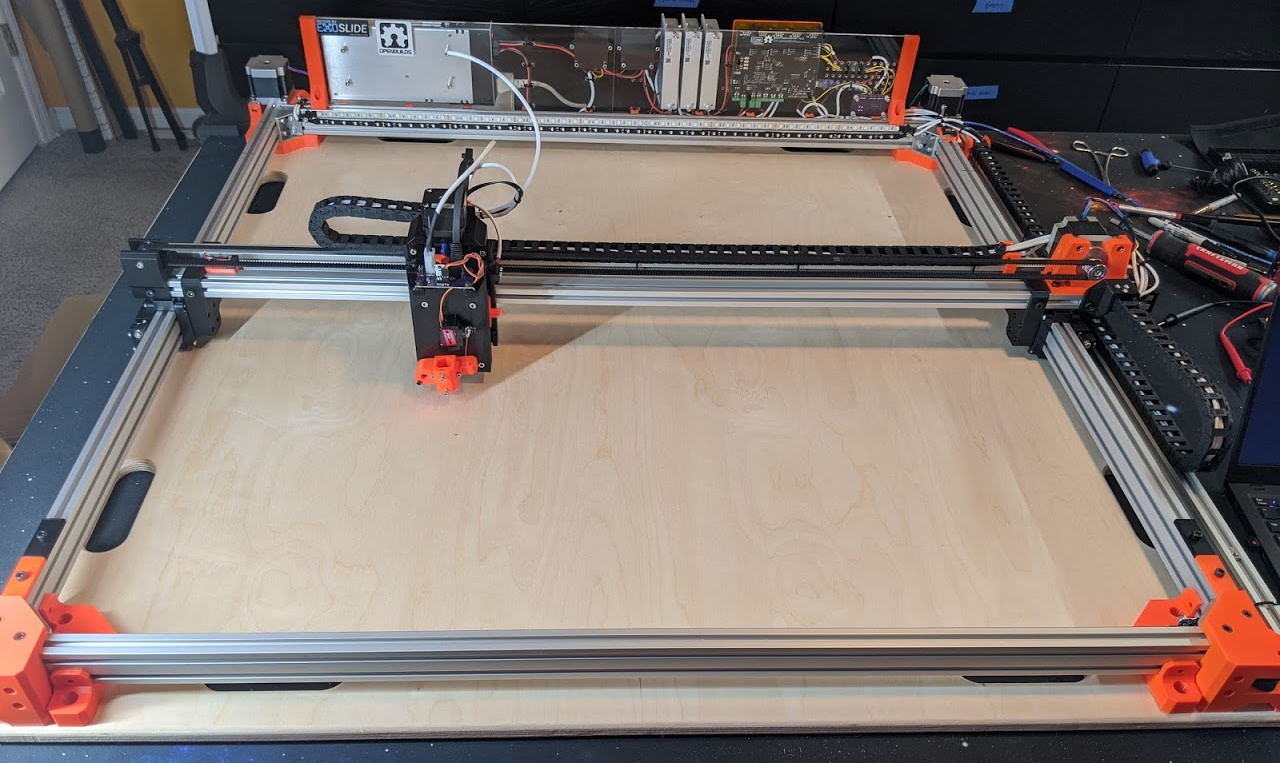
- 800mm x ~750mm working area (Y axis depends on current tool)
- 2040 Aluminum extrusion frame
- ExoSlide Linear slides for both axis
- 9mm wide GT3 heavy-duty belts
- Nema 23, 1.2 Nm motors (1 on X and 2 on Y)
- DM542Y 4A motor drivers
- 40mm travel Z-axis
- SmoothieBoard 5X
- Interchangeable tool heads with common power and signal connectors
- 5V, 12V, and 24V available for tools and accessories
- Travel speeds up to 1000mm/s on X and 500mm/s on Y
- Built in white and UV LEDs
Tools
Originally I had considered creating a system that could do automatic tool changes, likely using the new E3D tool changer specification. But I quickly realized that I wanted to have larger tools than that could support and that a 3 minute manual change was perfectly fine for my needs. It could certainly support an automatic change system, I just didn’t need the feature. But getting even a manual tool change down to a couple minutes still took some careful consideration.
The core of the system is a series of custom designed circuit boards each with the same mounting pattern, basic size, and electrical connections.
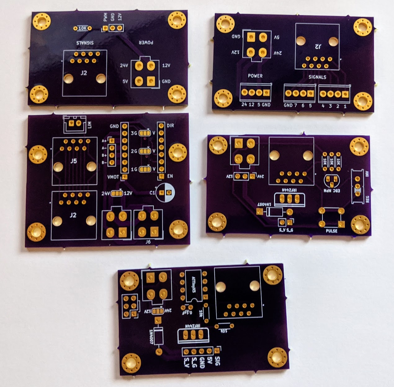
The signal input is handled via a standard shielded ethernet cable while ground, 5V, 12V, and 24V power are supplied by a 2x2 molex connector. This allowed me to simply run a standard Cat6 shielded ethernet cable and 4 wire power cable through the drag chains. Both the ethernet and molex connectors are also designed to be robust through many connect/disconnect cycles and are already designed specifically for carrying data signals and power, respectively.
By using an 8-pin ethernet cable, I also have plenty of room to grow in case any future tools need another signal. Right now the connections are as follows:
- Tool On/Off (non-PWM “laser” output from controller)
- Laser PWM
- Unused
- Unused
- Z-Step
- Z-Direction
- Z-Limit
- Ground
The Smoothieboard has the ability to set a “TTL” output pin which is required for some types of laser cutters. However, it was useful in this case as it flips to a high logic state whenever the laser PWM signal is anything other that 0. Basically every tool other than the laser requires this simpler on/off state. This signal gets utilized in some creative ways that will be described later.
The final part of the tool system is that it uses a standard M4 bolt mounting pattern on every tool. The X-axis carriage has a plate with captive M4 nuts and each tool can be simply fastened to this plate with M4x18mm bolts and then have the power and signal lines connected.
Z-Axis
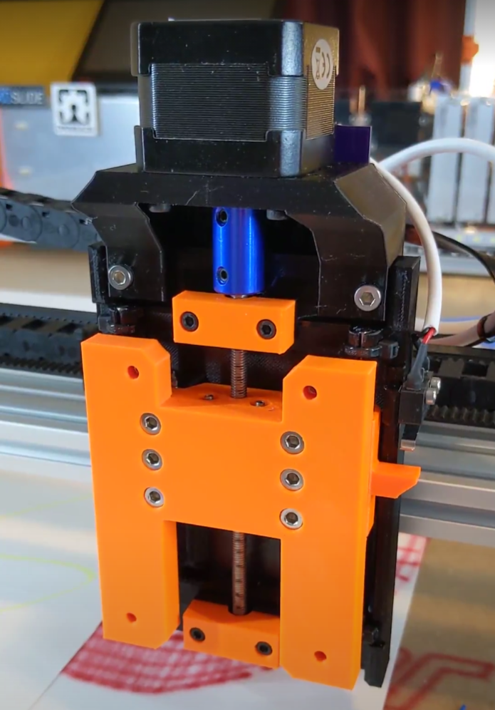
The Z-axis, design-wise, is more of a meta-tool and was honestly an afterthought during the process. While not strictly necessary for things like a pen-plotter I realized that it might be worth having at least a little Z movement available. Since the controller could support it without issue, I decided to go ahead as long as it didn’t cause more trouble than it was worth.
The design I came up with bolts to the X-axis with the same exact mounting system the rest of the tools use and then provides the reciprocal mounting surface for tools to be mounted on. The back plate contains a motor, M5 screw rod, and two 4mm linear rods. A front plate then contains four LMU4 linear bearings and a captive M5 nut. This allows for about 40mm of Z-axis travel with decent enough accuracy and incredibly low speed. I honestly hesitate to call it a real Z-axis as it was simply designed to be as compact as possible and provide very basic up and down movement during setup but then to never move again.
One of the tricker bits of this axis, however, is the custom PCB that not only passes along the power and signal lines but contains a built in motor driver. Controlling the motor directly from the Smoothieboard would require 4 dedicated lines just for the motor and at least one more for the Z-axis limit switch. But I realized that I already had power available and then could control the motor with only step and direction signals. With the limit switch I was at three wires total, saving me two. This also prevents any issues that might arise from having over 2 meters of stepper motor wires running next to signal lines.
Laser
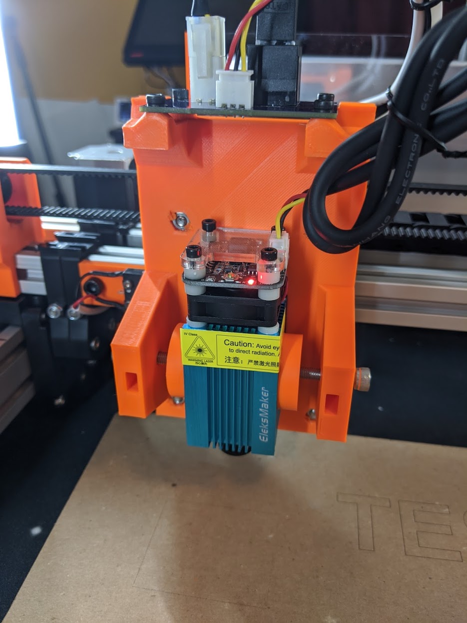
You’ve got to have at least one laser!
This was the first tool design because it was the simplest. There’s nothing special; just power, a PWM signal, and a way to hold the laser.
Because I literally have a box full of various diode laser modules (from Engravinator testing) I decided to forgo using any of the built in mounting holes on the modules and instead build what amounts to basically a clamp. M5 bolts come in from both sides, with large pads and just hold the module in place with pressure and friction. This allows me to hold a wide variety of modules without much fuss.
Pen Lift
The bread and butter of the plotter world. I, of course, had to have a pen lift mechanism - otherwise how could I ever be part of #plottertwitter?
This went through multiple revisions before I finalized the current design:
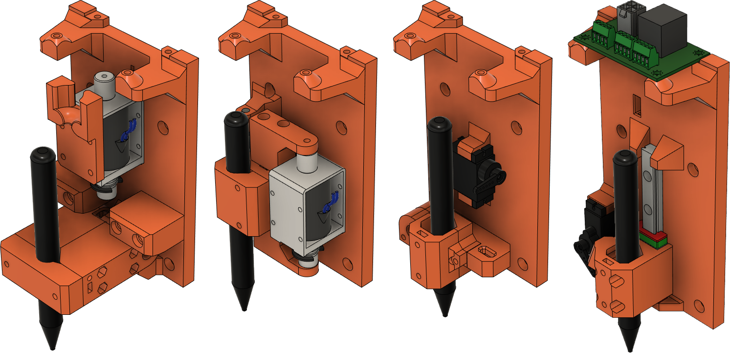
In the end, I remembered my “Spared no expense” mantra and just went ahead with using an MGN9 linear rail. This may seem like complete and utter overkill but it vastly simplifies the design. For one, the most important thing for a pen lift mechanism is to be able to lift the pen and place it back down in exactly the same spot. Previous versions that used a levered mechanism were not particularly great at doing this. But the MGN rail is already designed to move smoothly in exactly one dimension. This also allowed for the whole system to be basically 3 components. The rail, a pen holder that bolts to the rail, and a servo.
The control setup is where things get interesting. Technically the smoothieboard can control a servo directly, however this would require yet another control line (even if there are space for them) but, more importantly, would require changes to the controller config and the control software. Instead the hookup PCB contains an ATTiny85 microcontroller that does little more than read the tool on/off signal and then output a servo control signal.
This allows for the software to not even be aware that it’s controlling something other than a laser. The only tweak that generally needs to be made is a very slight delay at the start and stop of each line to allow the pen to move.
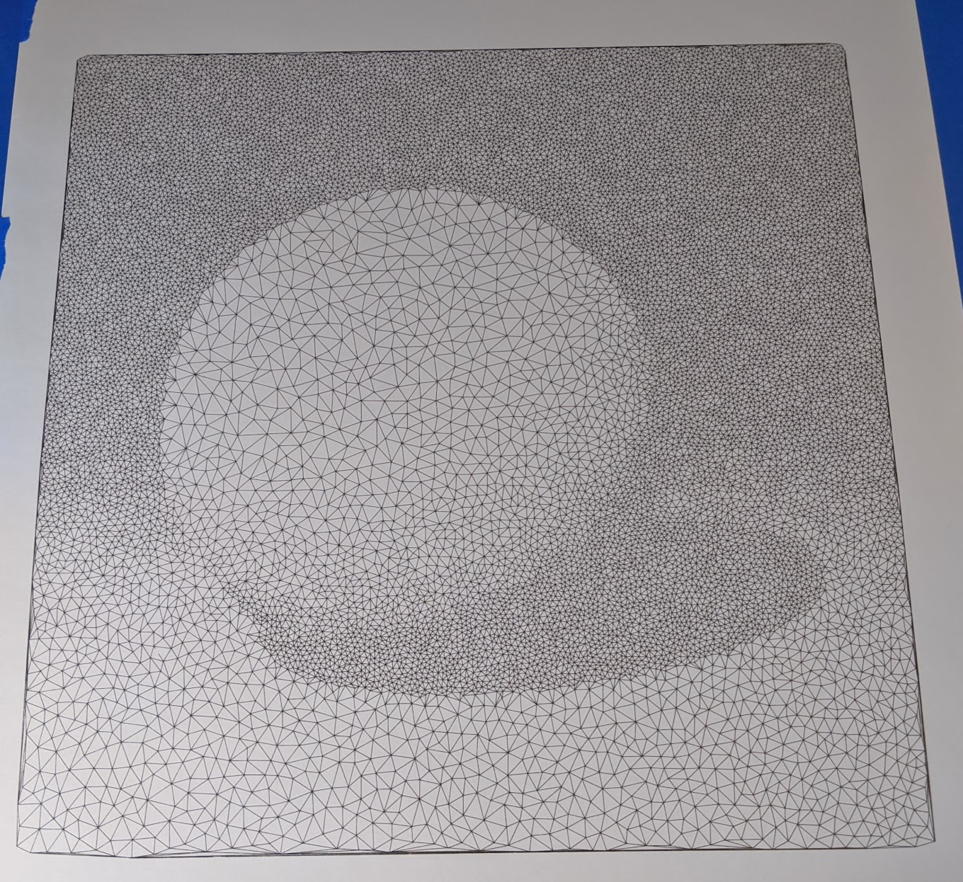
It’s absolutely amazing to be able to do huge plots like this 500mm x 500mm Delaunay sphere.
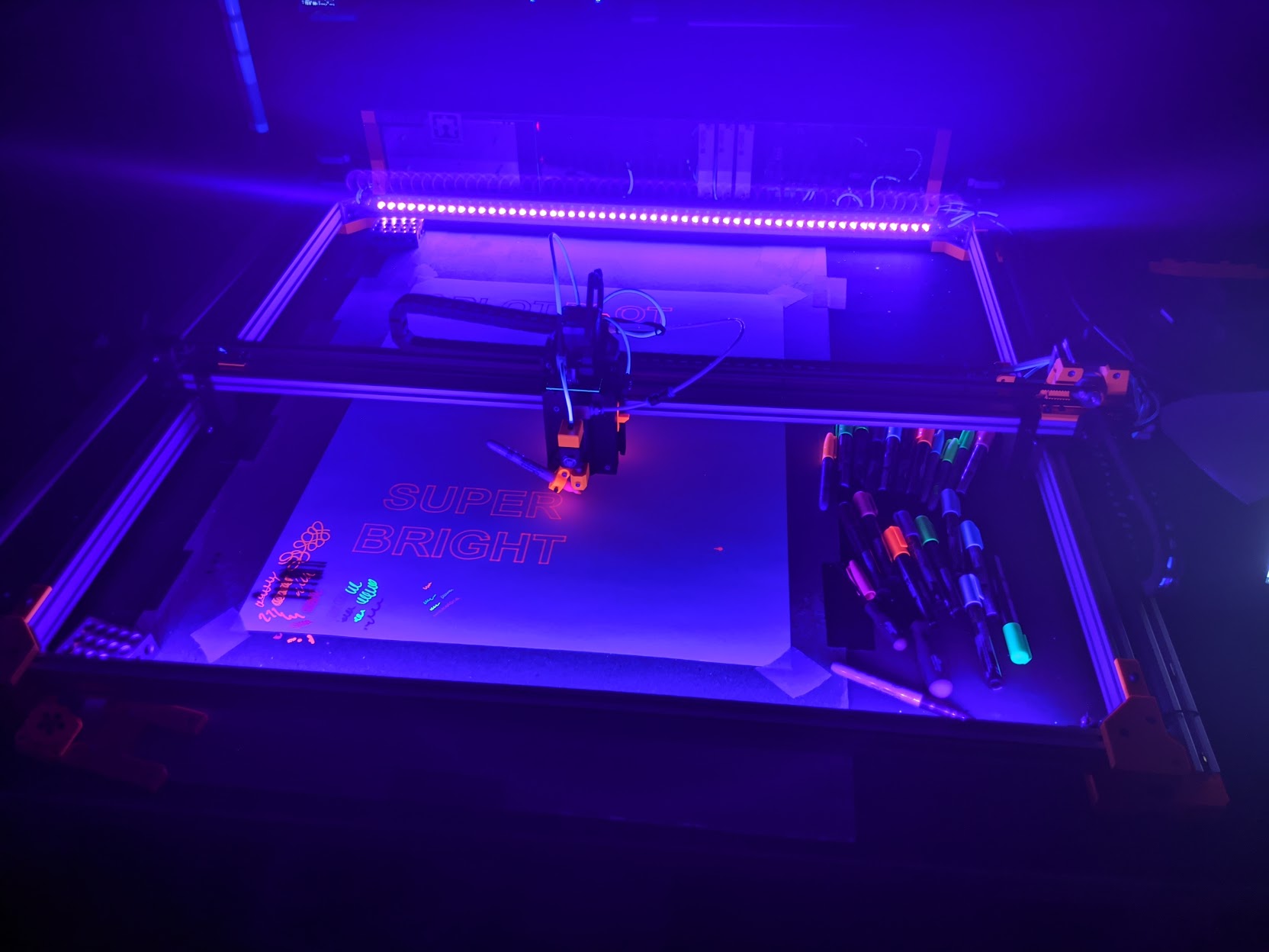
Airbrush
This was my first attempt to make something out of the ordinary. I found a couple very old videos of actual, proper, paint airbrushes being attached to a CNC machine but they had to be modified to work in that orientation. But the thing that kept coming back to mind was this cool marker airbrush made by Copic. Based on that I tried to copy the same basic concept but with a standard Sharpie marker. Amazingly, even the first rough proof-of-concept worked surprisingly well.
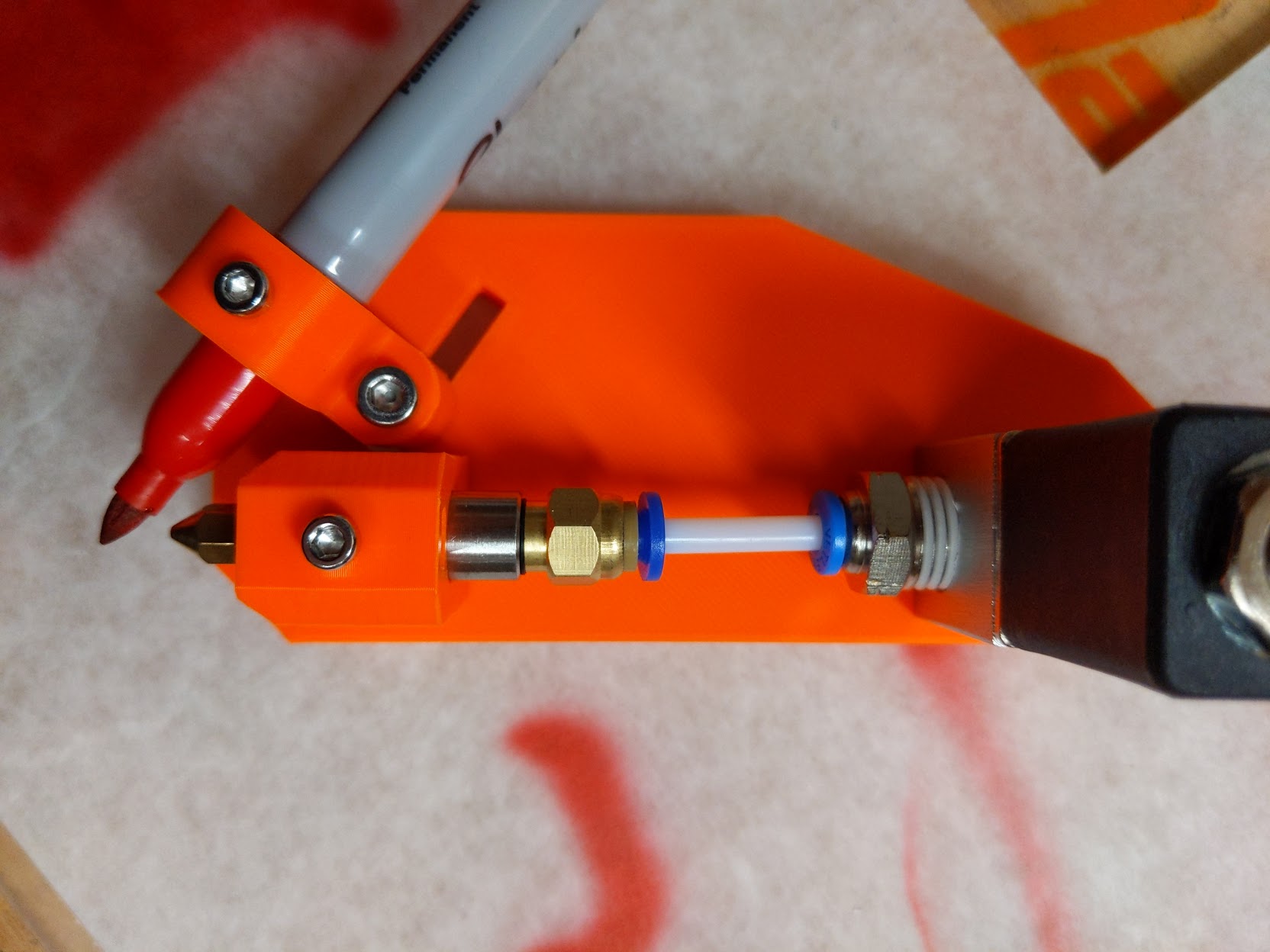
In order to make things as simple as possible I used a basic 24V pneumatic solenoid which was then connected to a coupler and a standard MK8 style 3D printer nozzle. Aside from being abundantly available it also allows for quickly changing the nozzle size and therefore change the flow and pressure characteristics.
I tried a box full of various markers and, honestly, the best was always the venerable Sharpie. They are consistent and last a long time before going dry.
Like the pen lift mechanism, the airbrush is controlled via an ATTiny85 but with a MOSFET at the output instead. The ATTiny is not strictly required in this case but it allows me to do some signal filtering as well as make sure that the MOSFET gets enough current to be driven quickly.
Oh… and purely because Sharpie makes fluorescent markers, it has UV lights :D
Camera

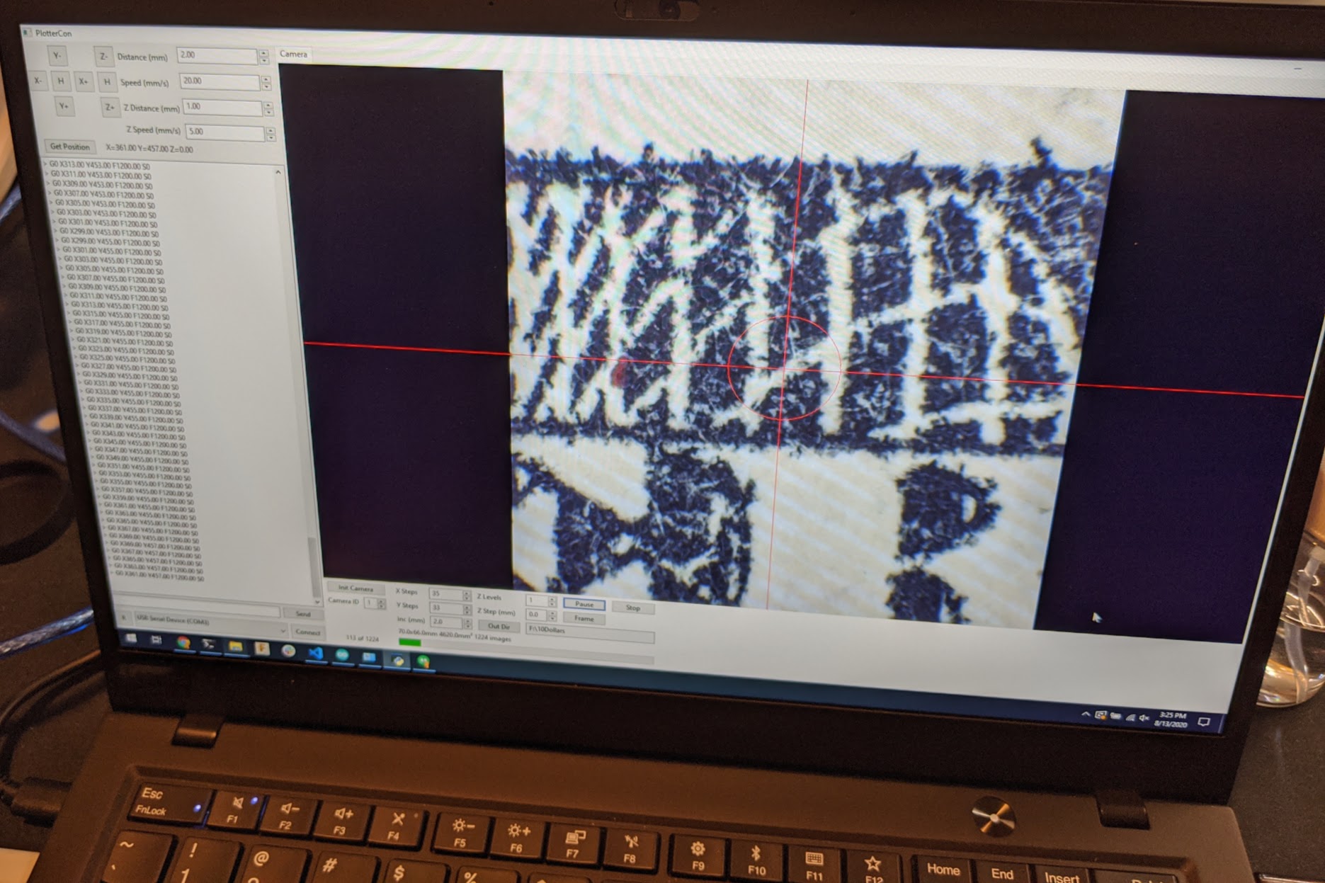
Yes - a camera. This is where I started to get a little crazy. The idea was to mount a high resolution camera with a microscope lens that could be precisely moved around to take a grid of pictures which could be later stitched together. As it stands right now this is still in the proof of concept stage. It basically works but I still need flesh out the process some more.
The hard part was not really the hardware in this case but the control software. This called for something that could both control the movement of the machine but coordinate that movement with taking pictures from the camera. What I eventually came up with is very much in the alpha stage - I call it PlotterCon. It’s written in wxPython and uses the printcore module that’s the core of Pronterface for all machine communications.
I’ve designed the software to be a framework for any custom plotter control. For example, I would like to make a stippling tool and would need to likely find circles in an SVG file and process them into individual points to be impacted by the tool. This should be easy enough to add to PlotterCon since all the core control features already exist.
Once images are captured it’s mainly a matter of post-processing everything into a single image. There’s no lack of information on automatic image stitching online so I won’t repeat it here but it’s still not exactly an easy process. Especially when you need to process over 1200 5-megapixel images into a single 1500 megapixel image, such as this one of Alexander Hamilton on the $10 bill.
What’s Next?
I have more tools in mind and will be continuing to hack at the design as needed. Just a few new addons I have in mind:
- Drag knife
- Stipple spike (solenoid driven spike to make stipple art with actual punched holes)
- Automated punch embroidery
- Mini plasma cutter
- 3D printer with extreme XY and very limited Z height
While all the design files for the entire machine are available (and linked below) there is no plan or desire to release this as a kit or even with extensive build documentation, like with the Engravinator. The full Fusion 360 project is available and if you use my design to build your own I’d love to see it! But you’ll have to handle the build with just the design files alone :)
Design Files
Basically everything you need is contained in the CyberPlotter GitHub Repo, including:
- All PCB KiCAD designs
- Fusion 360 project files
- A mostly complete Bill of Materials
- Smoothieware configuration
While I won’t be providing a step by step build guide or anything please don’t hesitate to reach out on the Maniacal Labs Forum if you are interested in building all or even part of this machine and have questions.
I’ve also put up a gallery of a handful more random pictures from throughout the design and build process on Google Photos.
And if you stay tuned to our website you might even get to see something that fits nicely between the CyberPlotter and the Engravinator soon… that only takes a couple hours to build :)