555 IC XXL
A few days ago, I saw this kit from Evil Mad Scientist (by way of Adafruit). My first reaction was more or less �… That�s brilliant!� I love projects that have a healthy dose of wackiness as part of the recipe. Don�t get me wrong, I appreciate projects that are purpose-built to accomplish a goal. But this kit in particular jumped out at me for two reasons.
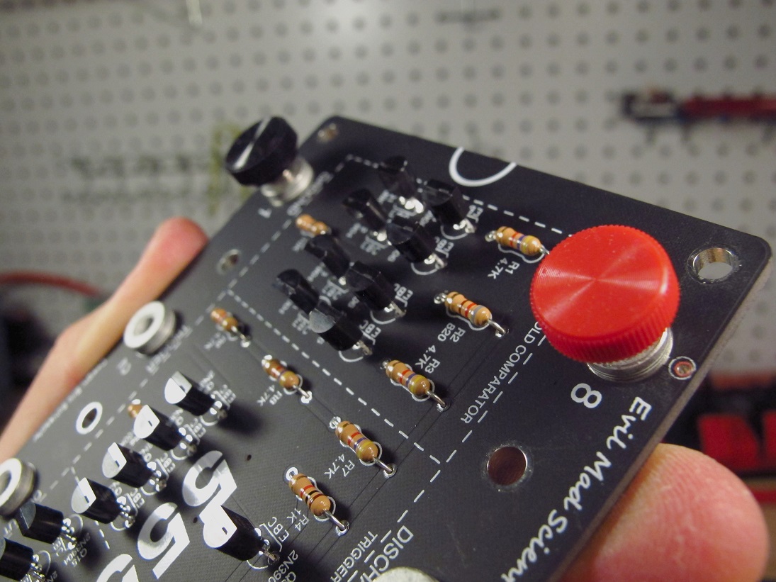
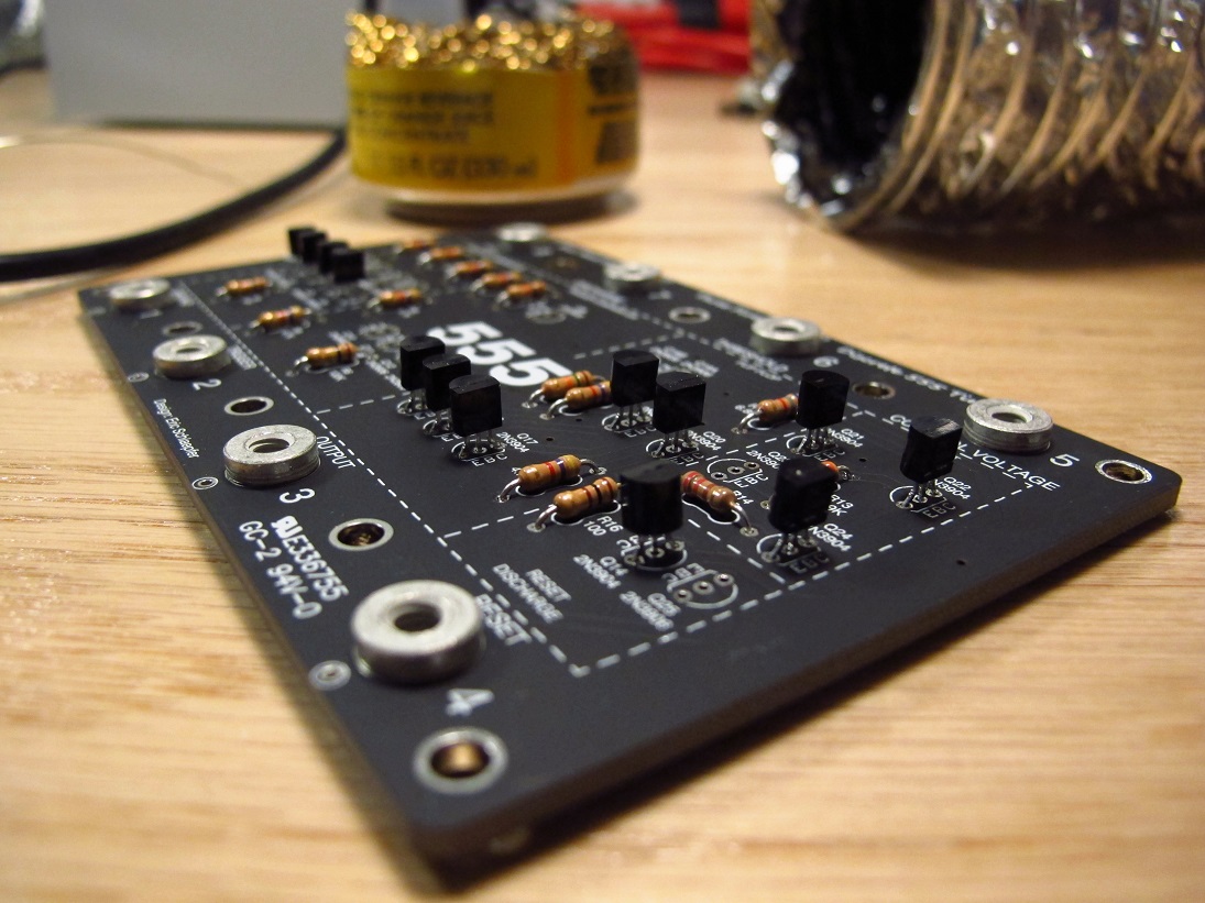
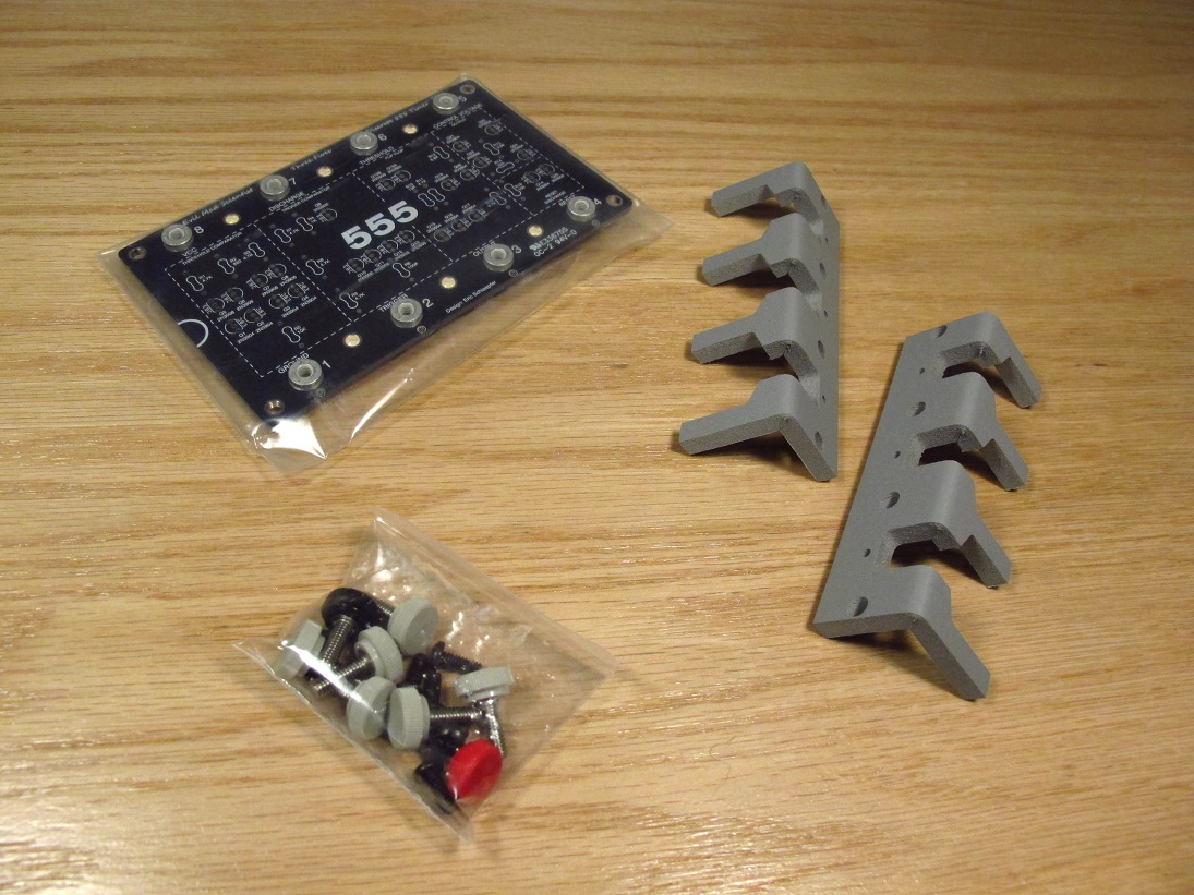
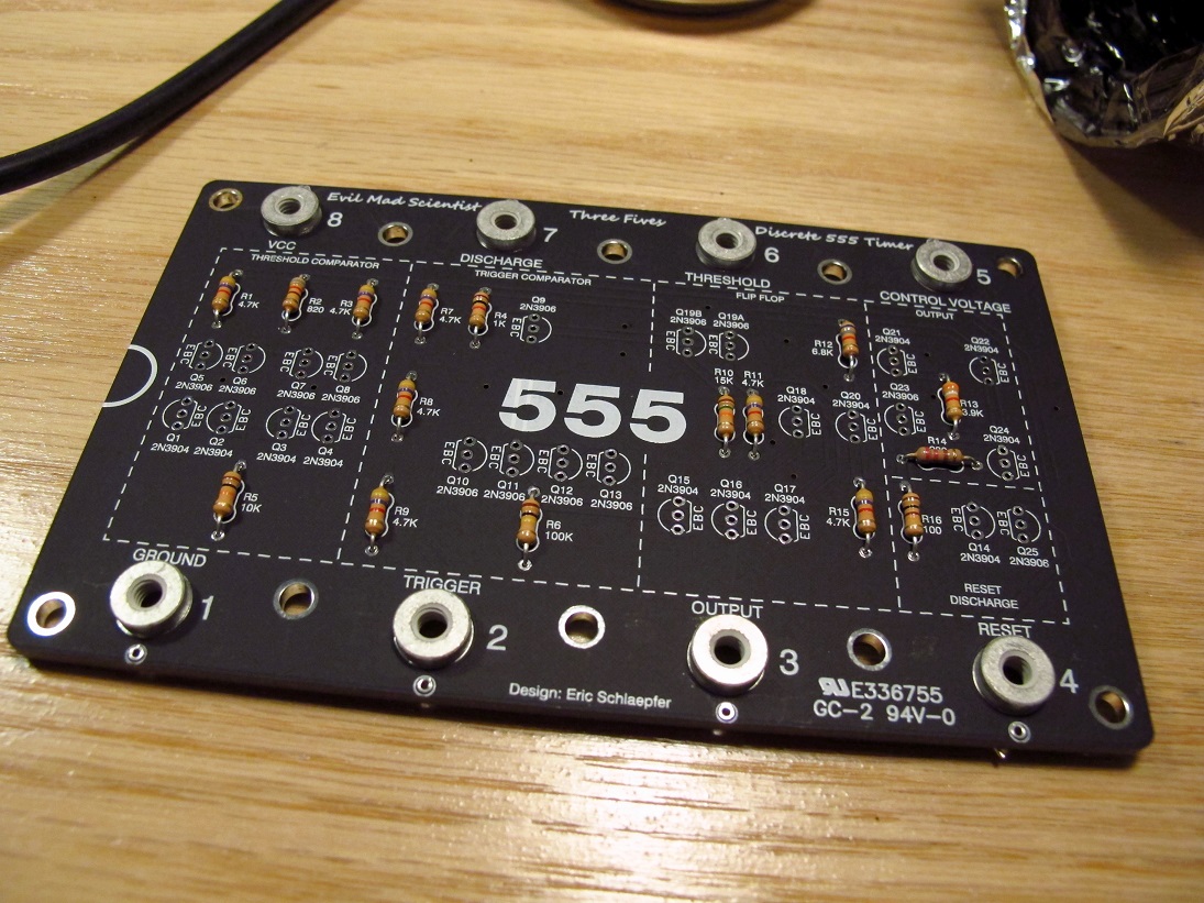
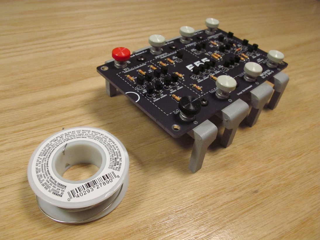
But before that, the �What.� This kit takes the internal workings of a 555 IC and, with resistors and transistors, re-creates all the functionality of the humble little chip. Plastic �legs� complete the IC persona, and screw terminals allow for easy hook-up connections to protoboards or �dead bug� style circuits. The PCB is quite hefty, and the silk screening divides the different block components of the 555 circuit. It�s a great piece to look at, and it just happens to be completely functional. Bonus points.
First, the kit is most clever. Kit designer Eric Schlaepfer basically ripped the lid off of a 555 IC and blasted the thing with an Embiggening ray. Sure he could have just thrown the components onto a breadboard, but that�s no fun. The inclusion of the legs and the �notch� on the silkscreen instantly inform anyone familiar with electronics what this is. Of course, the giant �555� printed on it doesn�t hurt either. The giant terminals are a nice functional and aesthetic touch. So were I a judge on Iron Chef: Electronics Edition, I would award full points for creativity and originality.
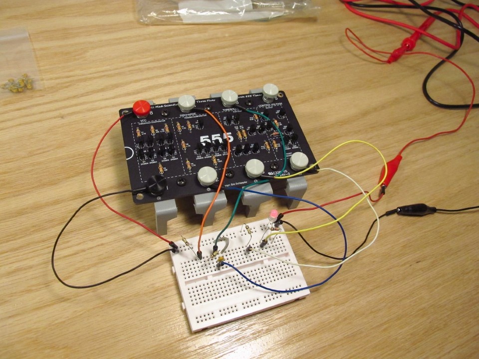
Second, upon seeing the kit and instantly knowing that I wanted one, I knew that I would need to brush up on my 555 knowledge. I admit, I�ve played with 555s in the past, but I�ve never given much thought to the internal workings. So after having some fun putting the kit together and testing the included (astable configuration) test circuit, I took to the Tubes and sought out some diagrams and videos explaining the design and operation of the small but mighty 555 timer. I’ll include some of my findings below.
In a nutshell, the 555 timer works by using two voltage comparators and a flip-flip to generate pulses on the output pin. The two most common configuration modes are astable, in which the external circuitry causes the 555 to generate a constant pulse waveform, and monostable, where an external trigger causes the 555 to generate a single pulse. One of the key components to these common circuit configurations is the capacitor. When the capacitor reaches a certain fraction of the supply voltage, the flip-flop is �actuated�, the output pin goes high or low, and the capacitor will start discharging or re-charging. Obviously this is a very simplistic explanation, but the rate of capacitor charge and discharge (governed by capacitor and resistor values) are key to the timing applications of the 555 IC.
So to sum up, yay for creative kits that cause you to go out and (re)learn stuff! The cool thing about the 555 chip is that it is very much a building block to bigger things. There are plenty of resources out there for 555 applications and project ideas. I�d like to thank Eric Schlaepfer for his awesome kit idea and Evil Mad Scientist for helping make it available to the masses! I think it quite possible that you might see the 555 creep into future Maniacal Labs projects.
-Dan
Here are some resources I found while brushing up on the subject:
Of course, Wikipedia has a good synopsis of the 555, as well as some of the more in-depth maths detailing the particulars of how the different configurations function. en.wikipedia.org/wiki/555_timer
The datasheet from Signetics, who developed the 555 in 1971: www.datasheetarchive.com/dl/Scans-064/DSA2IH00140042.pdf
From the Sparkfun series “According to Pete”, Pete walks through some 555 basics.
This video is long, but the link takes you to right where he demonstrates the inner workings of a monostable 555 circuit. The whole video is definitely worth a watch. youtube.com/watch?feature=player_detailpage&v=SX01x1z7fTY#t=610
A few projects featuring one or more 555 timers: 555-timer-circuits.com
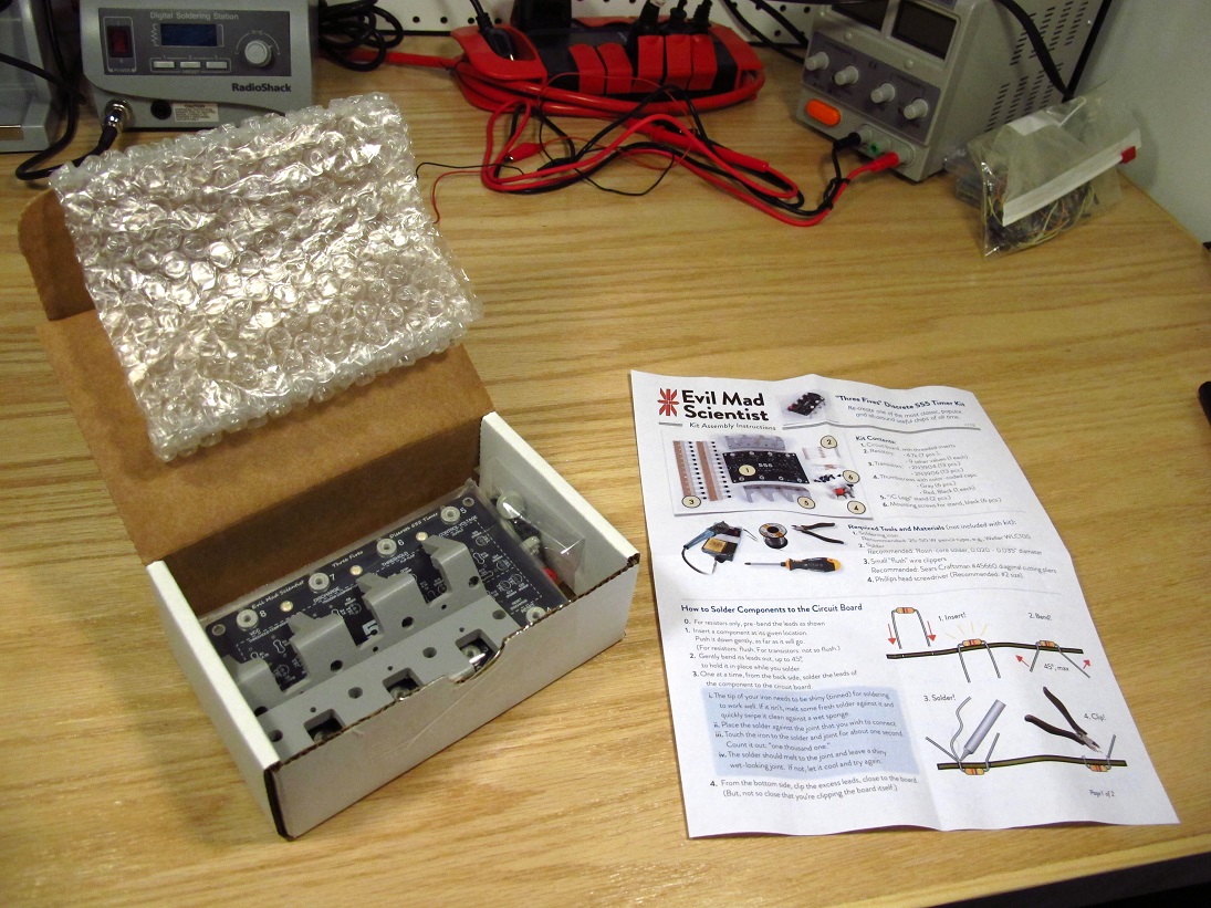
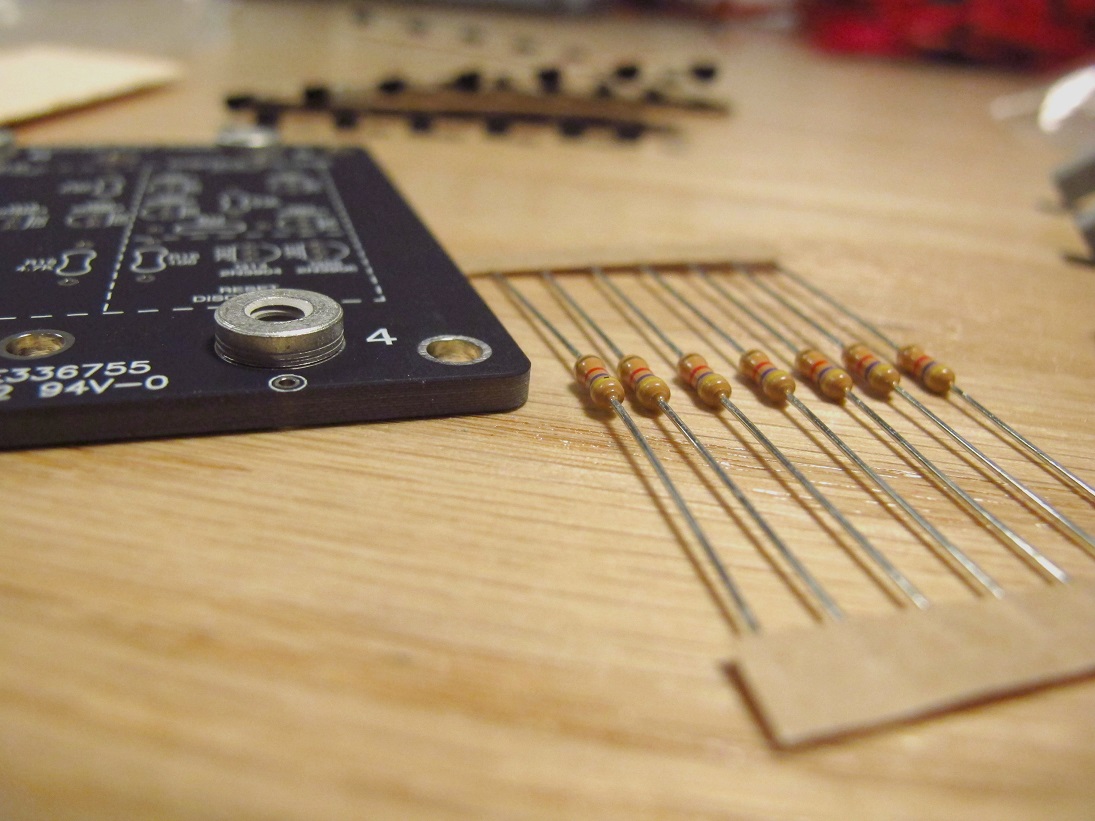
And some more pics from my build:

